
LedBorg - An ultra bright RGB LED add on board for your Raspberry Pi
Lesson plan
Installation of the new LedBorg softwareLesson 1. Our first Python example
Lesson 2. Simplifying the code
Lesson 3. Produce a sequence of colours
Lesson 4. Taking user input
Lesson 5. Brightness levels (PWM)
Lesson 6. A simple dialog (GUI)
Lesson 7. Using a pre-made dialog
Brightness levels (PWM)
In the previous lessons we have only used the seven colour combinations LedBorg can produce by turning theHow can we get a better range of colours like the example pictures show?
What we need is a way of giving the channels less power so we can dim them.
One way of doing this is using Pulse Width Modulation.
Pulse Width Modulation (PWM)
PWM is commonly used technique to make a digital output approximate an analogue output.The difference between analogue and digital outputs is that a real analogue output can produce differing voltage levels, whereas a digital output can only produce a fixed number of output levels, typically just on or off.
The GPIO pins of the Raspberry Pi can either output 3.3V or 0V, which we will refer to as high and low.
On the LedBorg the chip converts these high and low signals to be 5v or 0v, they are still only capable of the two levels.
If we want the red channel to be half on we would need to give it 2.5v, between the high and low levels.
We can approximate this by toggling the output between high and low:
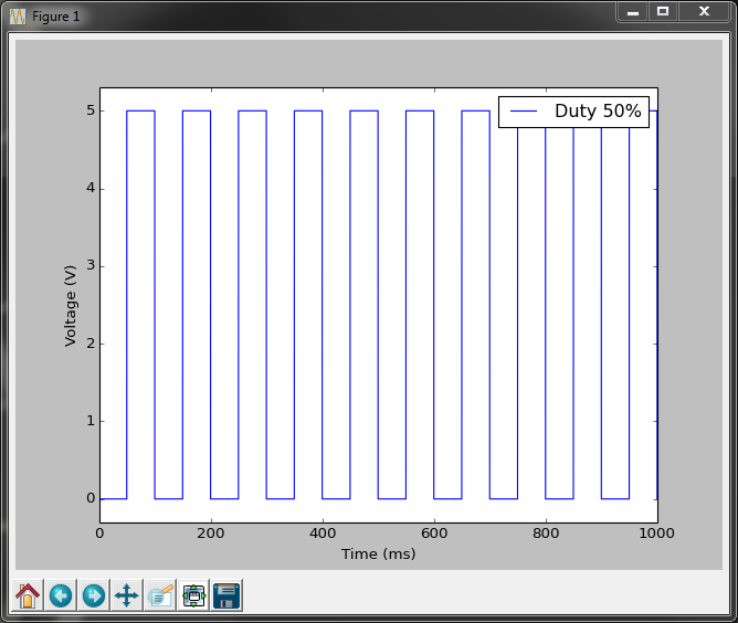
This is the basis of PWM.
With PWM we can vary two things, how often the pulses happen and how much time they are high or low.
How often they happen is usually set by some limitation, for example the Raspberry Pi can only change the GPIO pins up to a certain speed, this means the shorter the time interval, the less control we have of the high vs low ratio.
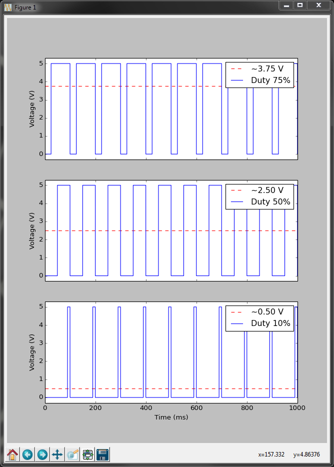
The ratio between the high and low states is usually expressed as a percentage of how much time the pin is set to the high state for, this is known as the duty cycle.
Varying the duty cycle allows us to produce different voltage approximations, so the brightness of our LED should match the duty cycle percentage:
Now we need to make Python perform this PWM functionality.
It turns out the hard work of making the GPIO pin change quickly has been done for us by the WiringPi library.
It is time to make a brand new script which uses this PWM functionality which will allow us to extend the range of colours we can display with LedBorg.
The improved SetLedBorg function
We start by importing our libraries as before#!/usr/bin/env python # Import library functions we need import time import wiringpi2 as wiringpi wiringpi.wiringPiSetup()No surprises there, we also need the constants for setting up our pins:
# Setup software PWMs on the GPIO pins PIN_RED = 0 PIN_GREEN = 2 PIN_BLUE = 3 LED_MAX = 100We now have a new one,
LED_MAX.LED_MAX will control how much control we have over the PWMs:- Larger value = more duty cycle options but slower rate.
e.g. a setting of 255 would give 256 × 256 × 256 = 16,777,216 colours,
but it would run slowly and the LED may visibly flicker. - Smaller value = less duty cycle options but faster rate.
e.g. a setting of 10 would give 11 × 11 × 11 = 1,311 colours,
it should also update too fast for the human eye to see. - Compromise = reasonable duty cycle options at a reasonable speed.
e.g. the chosen setting of 100 will give 101 × 101 × 101 = 1,030,301 colours,
it should be fast enough that most people will not see the LED flicker.
So we have our constants, now we need to setup the PWMs:
wiringpi.softPwmCreate(PIN_RED, 0, LED_MAX) wiringpi.softPwmCreate(PIN_GREEN, 0, LED_MAX) wiringpi.softPwmCreate(PIN_BLUE, 0, LED_MAX) wiringpi.softPwmWrite(PIN_RED, 0) wiringpi.softPwmWrite(PIN_GREEN, 0) wiringpi.softPwmWrite(PIN_BLUE, 0)This time we create a software based PWM helper for each pin which can be set to any whole number between 0 and
LED_MAX inclusive.We also set each PWM to 0, representing a 0% duty cycle → 0V → LED off.
So how do we make our
SetLedBorg function use this new functionality:
# A function to set the LedBorg colours
def SetLedBorg(red, green, blue):
wiringpi.softPwmWrite(PIN_RED, int(red * LED_MAX))
wiringpi.softPwmWrite(PIN_GREEN, int(green * LED_MAX))
wiringpi.softPwmWrite(PIN_BLUE, int(blue * LED_MAX))
What this function does is to take a fractional number for each between 0 and 1 inclusive, extend it to the range of LED_MAX, then uses the int function to get a whole number, e.g.:red = 0.3 → 0.3 * LED_MAX = 30.0 → 30It passes these setting on to the software PWMs so if we called:
SetLedBorg(0.75, 0.5, 0.1)We should get:
# A function to turn the LedBorg off
def LedBorgOff():
SetLedBorg(0, 0, 0)
At this point we could use any of the previous examples and they should work the same, but they will still produce the same colours they did before.What we need a more interesting example which produces some new colours.
Sweeping the LedBorg colours
We can put together everything we have learned from the lessons so far and sweep the various colour hues:
To do this we will need a loop which cycles a number between two values forever:
# Run until the user presses CTRL+C
print 'Press CTRL+C to exit'
while True:
# Loop over a set of different hues:
for hue in range(300):
As the comment says the script will exit when the user presses CTRL+C.This is not a function we have made it do, this is a standard Linux way of asking a program to stop.
The range function returns a list of numbers up to but not including the input, for example:
range(5) would return [0, 1, 2, 3, 4], we then loop over that new list.Now we need to work out the colour:
# Get hue into the 0 to 3 range hue /= 100.0 # Decide which two channels we are between if hue < 1.0: # Red to Green red = 1.0 - hue green = hue blue = 0.0 elif hue < 2.0: # Green to Blue red = 0.0 green = 2.0 - hue blue = hue - 1.0 else: # Blue to Red red = hue - 2.0 green = 0.0 blue = 3.0 - hueFirst we re-scale hue from 0 to 300 → 0.0 to 3.0.
Next we decide if we are in the first, second, or last third of the range.
After that we set the colour not in use to off, we set the other two depending on how close we are to each, for example 0.0 would be red only, 0.5 would be half way between red and green, and 2.1 would be 90% blue with 10% red.
Finally we set the LedBorgs colour and wait for a short period of time:
# Set the chosen colour SetLedBorg(red, green, blue) # Wait a short while time.sleep(0.1)What we should have is a gentle change in colour from red to green to blue and back to red.
This will get repeated until the user tells it to stop.
The complete script
The completed script can be downloaded directly to the Raspberry Pi using:wget -O lesson5.py http://www.piborg.org/downloads/ledborg-new/lesson5.txtRemember we make the script executable with:
chmod +x lesson5.pyand run it with:
sudo ./lesson5.pyWhat if we want to leave this script running in the background so we can carry on using the terminal?
We can make use of some standard Linux tools here.
There are two ways to do this:
- Start the script with an ampersand symbol (
&) at the end, like this:
sudo ./lesson5.py & - Start the script normally with
sudo ./lesson5.py
Once the script is running press CTRL+Z to pause the script
Now enter the commandbgto resume the script but in the background
fg to bring the script back to the foreground, then press CTRL+C like normal.
#!/usr/bin/env python

# Import library functions we need
import time
import wiringpi2 as wiringpi
wiringpi.wiringPiSetup()
# Setup software PWMs on the GPIO pins
PIN_RED = 0
PIN_GREEN = 2
PIN_BLUE = 3
LED_MAX = 100
wiringpi.softPwmCreate(PIN_RED,   0, LED_MAX)
wiringpi.softPwmCreate(PIN_GREEN, 0, LED_MAX)
wiringpi.softPwmCreate(PIN_BLUE,  0, LED_MAX)
wiringpi.softPwmWrite(PIN_RED,   0)
wiringpi.softPwmWrite(PIN_GREEN, 0)
wiringpi.softPwmWrite(PIN_BLUE,  0)
# A function to set the LedBorg colours
def SetLedBorg(red, green, blue):
    wiringpi.softPwmWrite(PIN_RED,   int(red   * LED_MAX))
    wiringpi.softPwmWrite(PIN_GREEN, int(green * LED_MAX))
    wiringpi.softPwmWrite(PIN_BLUE,  int(blue  * LED_MAX))
# A function to turn the LedBorg off
def LedBorgOff():
    SetLedBorg(0, 0, 0)
# Run until the user presses CTRL+C
print 'Press CTRL+C to exit'
while True:
    # Loop over a set of different hues:
    for hue in range(300):
        # Get hue into the 0 to 3 range
        hue /= 100.0
        # Decide which two channels we are between
        if hue < 1.0:
            # Red to Green
            red = 1.0 - hue
            green = hue
            blue = 0.0
        elif hue < 2.0:
            # Green to Blue
            red = 0.0
            green = 2.0 - hue
            blue = hue - 1.0
        else:
            # Blue to Red
            red = hue - 2.0
            green = 0.0
            blue = 3.0 - hue
        # Set the chosen colour
        SetLedBorg(red, green, blue)
        # Wait a short while
        time.sleep(0.1)
Continue to lesson 6. A simple dialog (GUI)