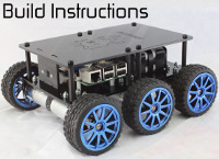
A robot called BOB

Submitted by Timothy Freeburn on Thu, 03/02/2017 - 17:10.
With the release of the new Raspberry Pi Zero W, we thought we would hack together a robot as it could take advantage of the small size of the Pi and the bluetooth connection to a controller.
We could have gone with a simple kit, but we wanted to show off our new motor controller - the ThunderBorg.
As the ThunderBorg has a DCDC on it to power the Pi from the one battery source all we needed was a Pi Zero W, some wires etc., two motors, wheels or tracks, and a battery source.
We wanted to use the bits we had lying around in the office. Hence the name BOB. The Bot of Bits.
We had lying around a Pololu Zumo chassis,some more powerful motors, a pair of quality 9V connectors for PP3 batteries, our brand new ThunderBorg controller and the brand new Pi Zero W.
If you would like to build one, please follow the instructions below! Then all you need to do is make an awesome video to go with it....
I hope you have as much fun watching as we had making the video! We couldn’t control our laughter as you might hear in the recording.
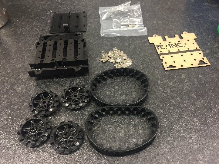 We started off with the Zumo kit. The main bits are tracks, wheels and a chassis.
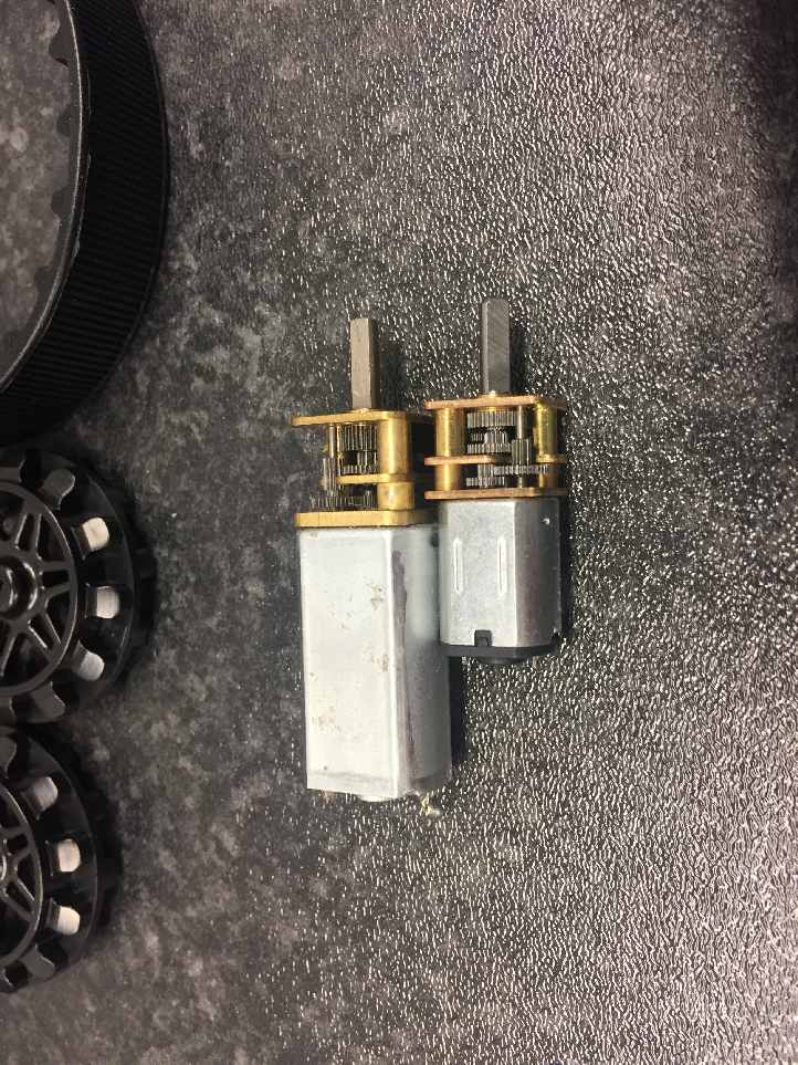 Although they look similar, the motors we had were significantly larger than the standard kit ones.
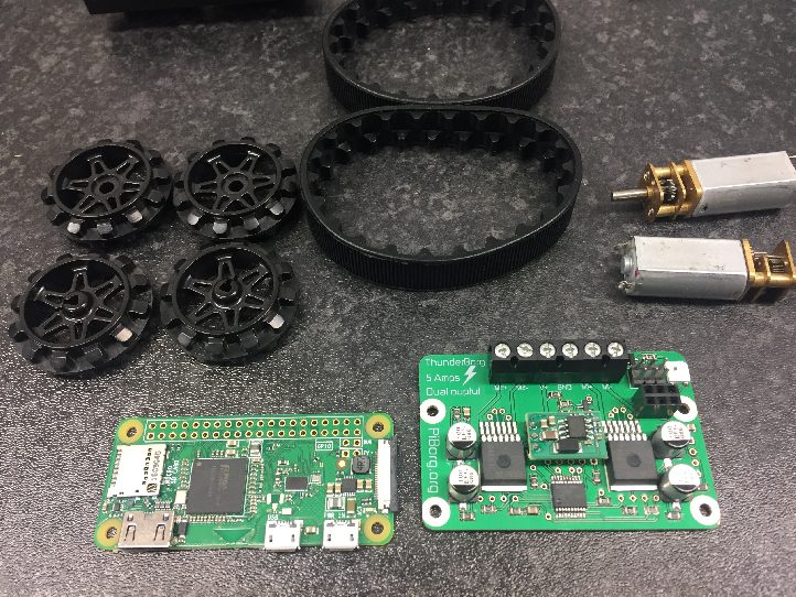 We took a Raspberry Pi Zero W and a ThunderBorg motor controller to power the robot.
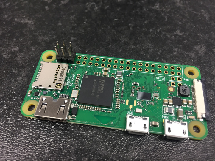 We soldered a 6 pin male header to the Raspberry Pi Zero W
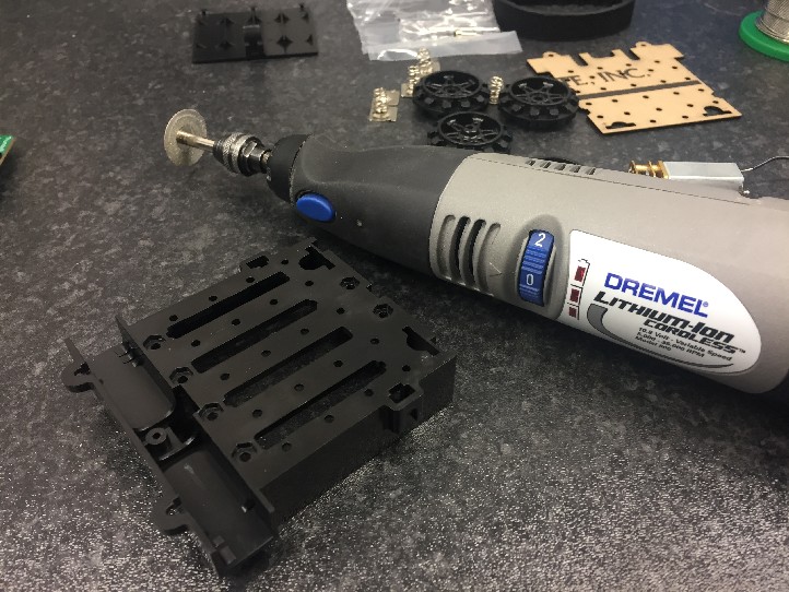 Next step was to cut up the chassis
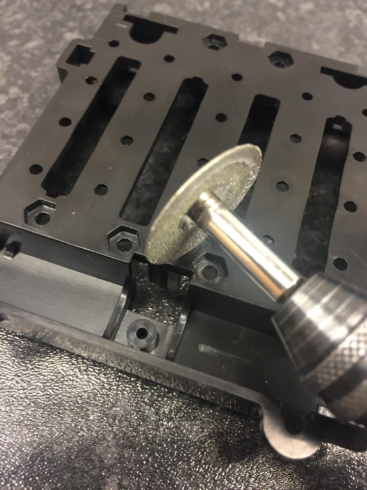 Cut at an angle as pictured
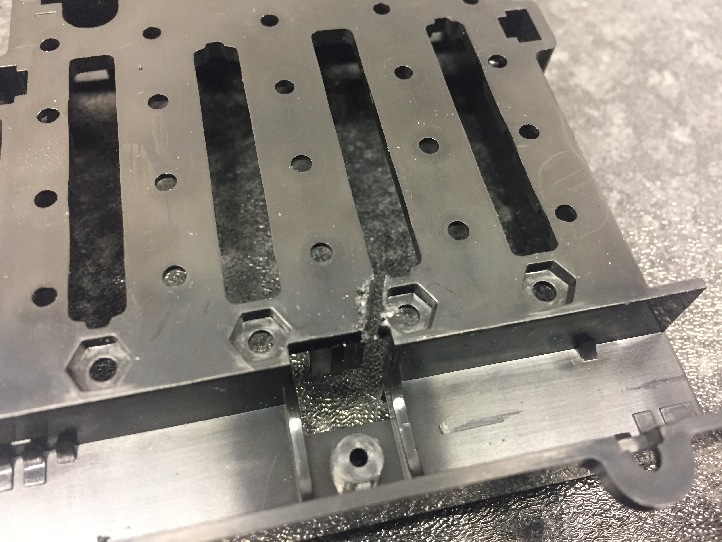 You will probably need to tidy up any cuts after you make them.
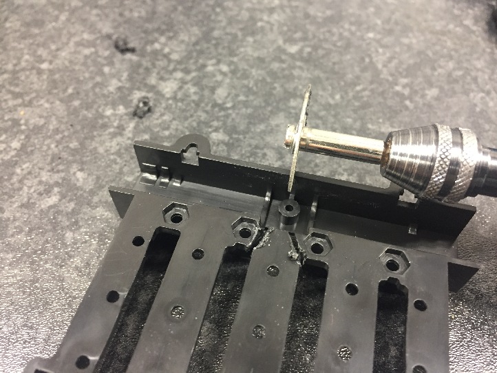 Repeat on the other side as pictured
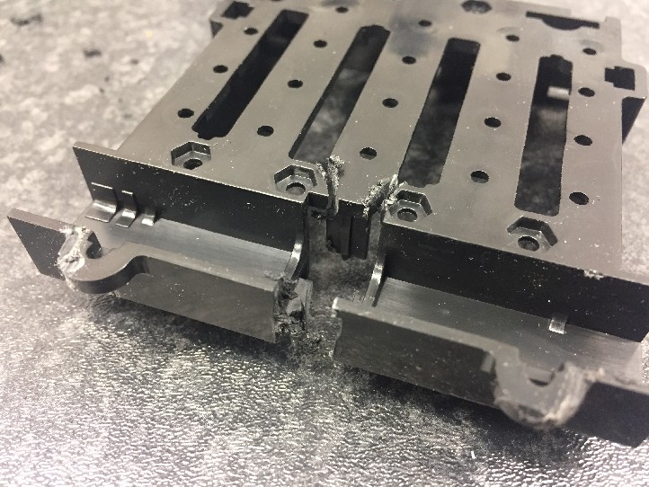 Also cut out center of the motor bracket end.
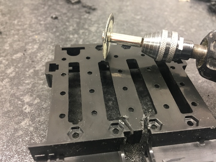 Cut the opposite side again at an angle
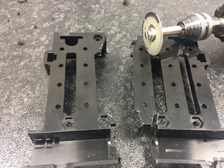 Now cut the center column out completely.
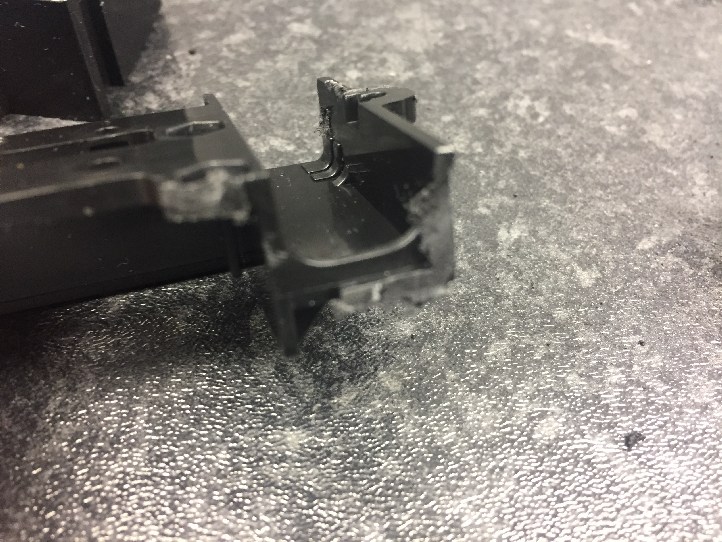 We will need to trim some parts of the motor mount to accomodate the larger motors.
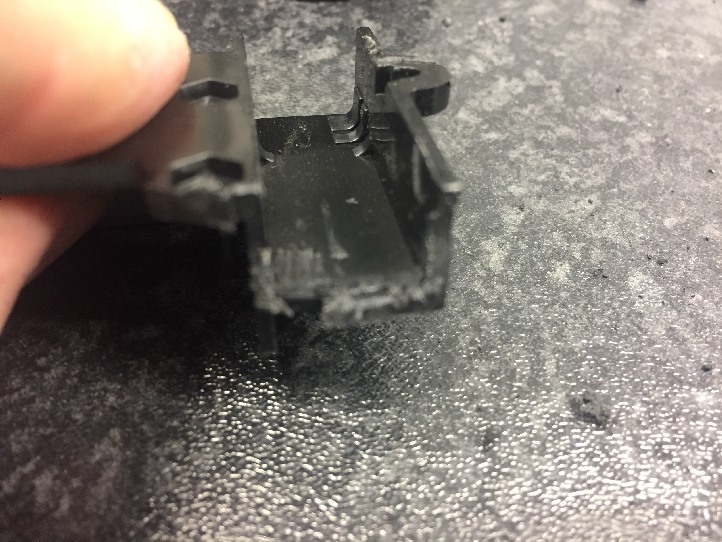 Here we have removed the motor end stops
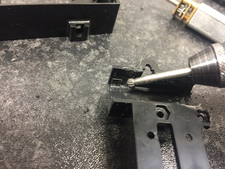 We will also need to remove the center tab as pictured
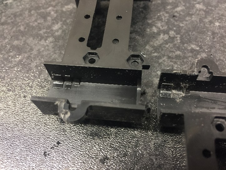 Here is a better picture of the center tab to remove. Before on left, after on right. This needs to be done to both motor mounts.
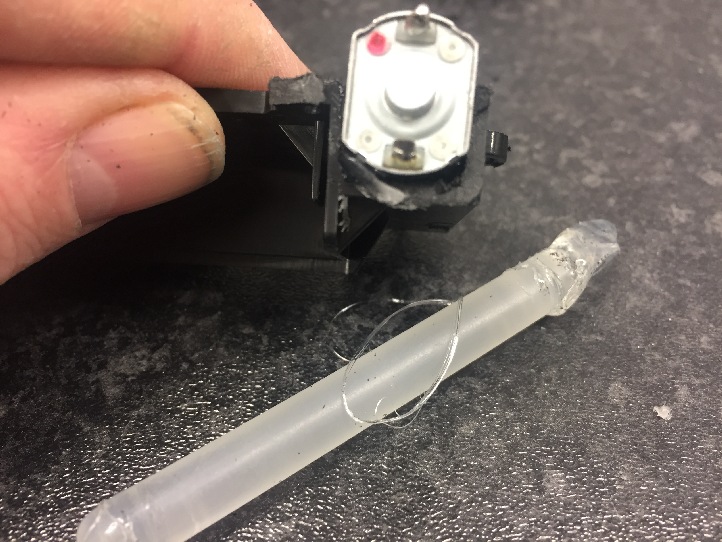 We will glue the motors in with hot glue. They sit in nicely when rotated 90 degrees.
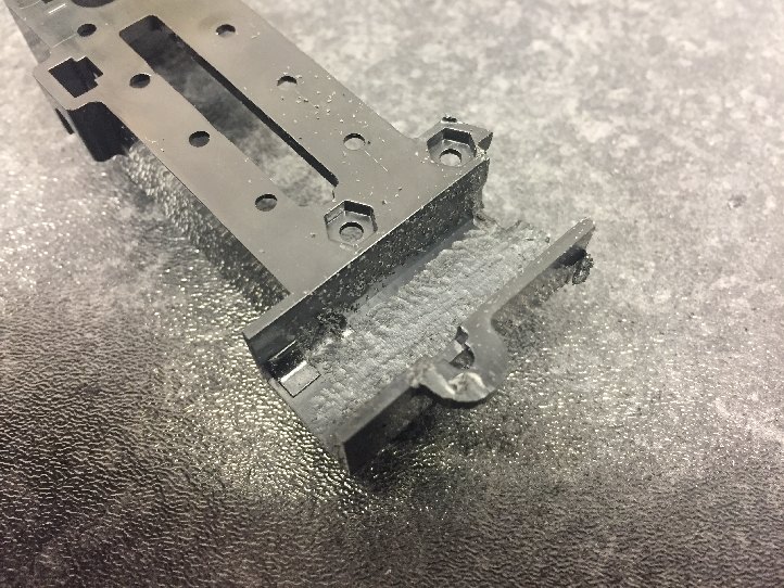 Rough the bottom of the mount so the glue will stick well.
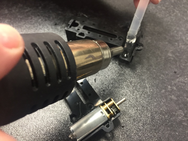 Heat up and place some hot glue in the mount.
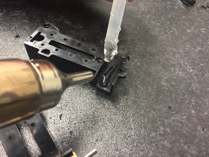 Be careful with the amount of heat, it shouldn't be so hot as to melt the plastic, but the glue should be tacky. Quickly insert the motor into position with the face closest to the shaft lined up against the edge of the mount.
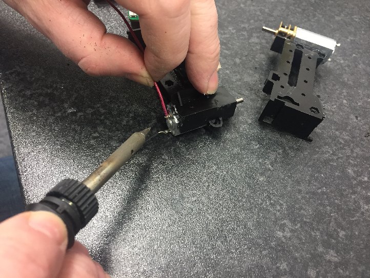 Solder a red cable onto the motor
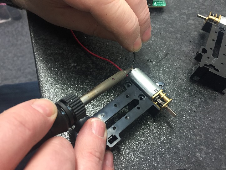 Repeat for a black cable.
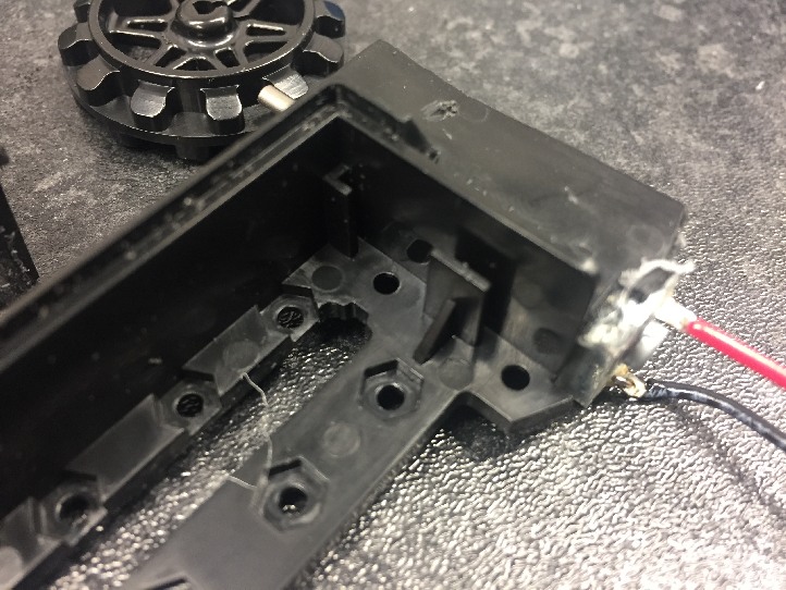 We will remove the tabs in the inside of the mount.
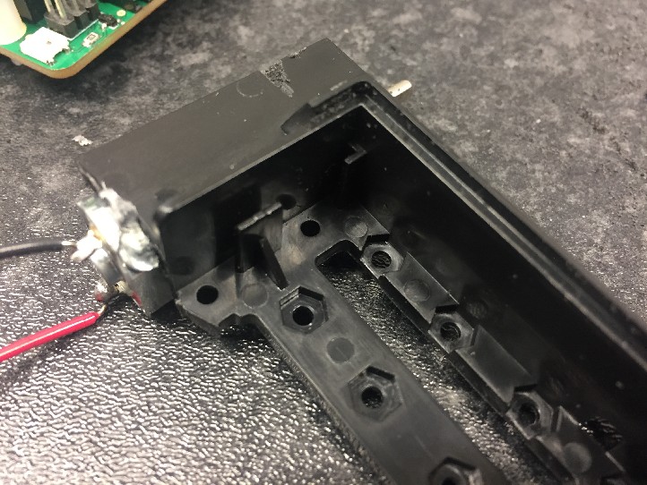 This is where the controller will live. We also need to do the same on the other side.
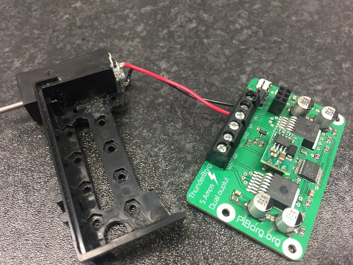 Once removed, connect the motor cables to the M4+ and M4- of the ThunderBorg motor controller.
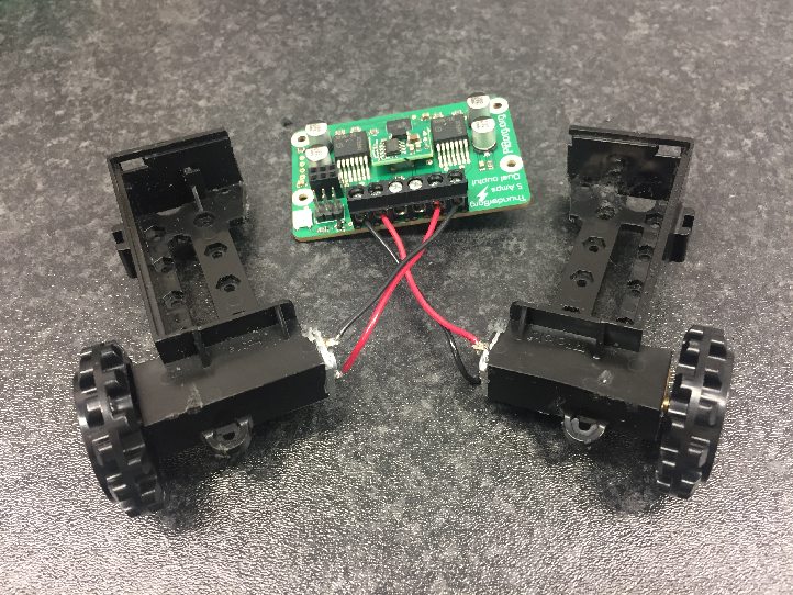 Repeat this for the other half.
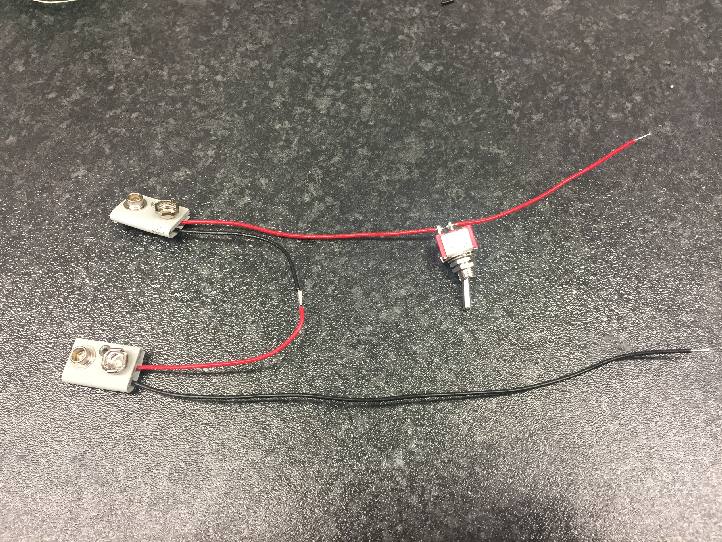 We have soldered on two battery straps, and a switch so we can quickly turn it on or off
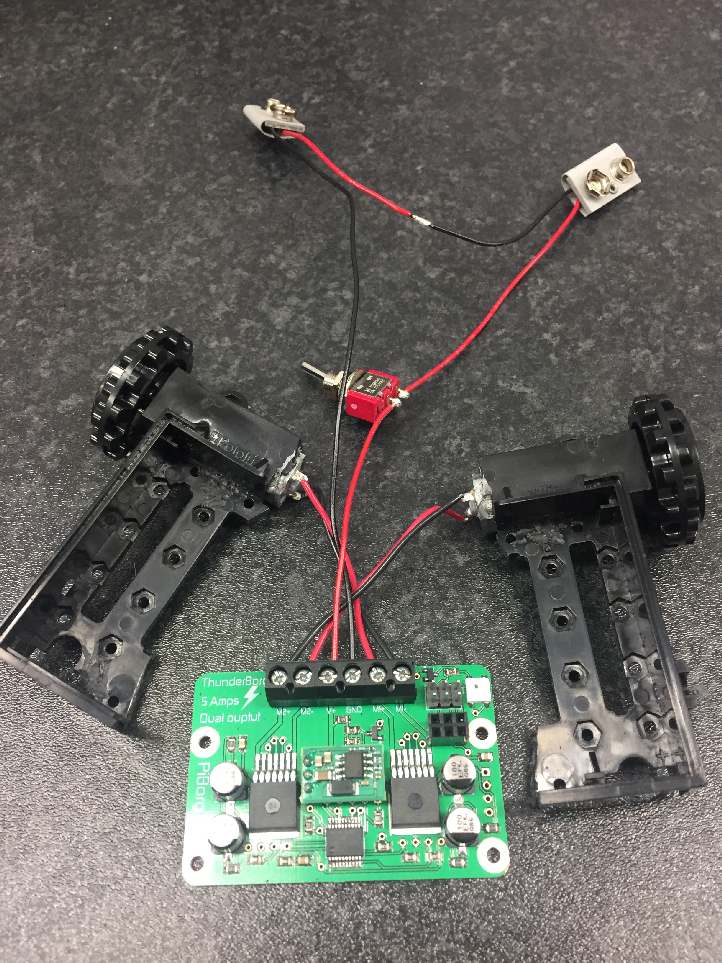 The switch and power connectors need to be soldered together and connected to the ThunderBorg as pictured.
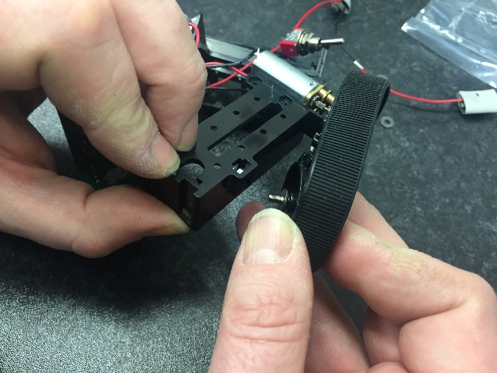 Add the wheels and put the tracks on. The nut sits inside the chassis, and don't forget to add a washer to let the wheel rotate freely.
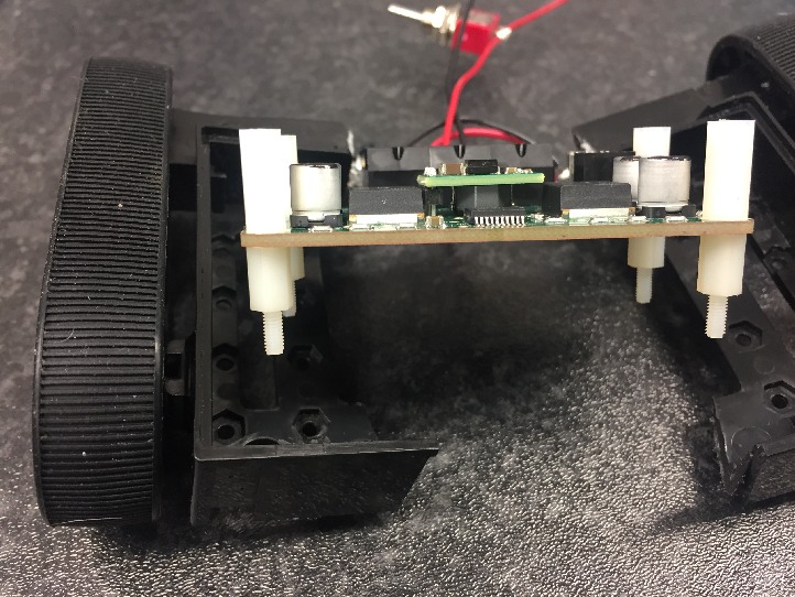 Put some M2 posts on the ThunderBorg, and more posts on the underside. These are avaialble in the accessories section of our website.
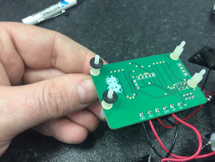 Add some washers to the posts
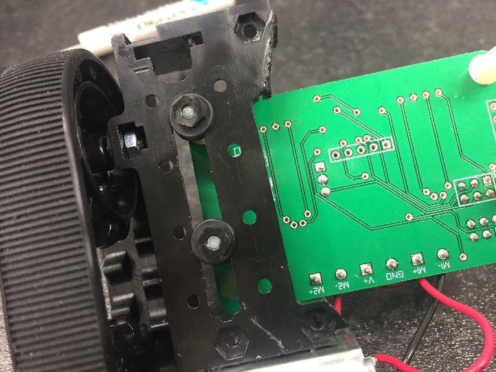 Add more washers on the underside, and m2.5 nuts.
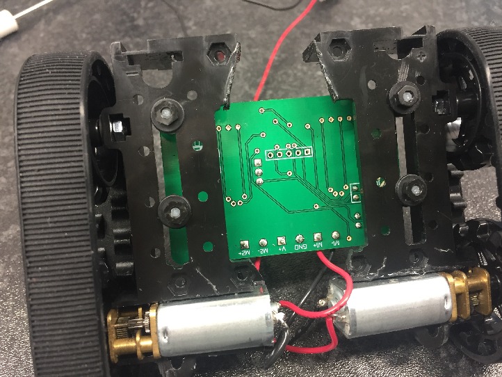 Repeat for the other side. The ThunderBorg will become the chassis for torsional forces in the robot. If you want to, you could add strengthening between the two sides.
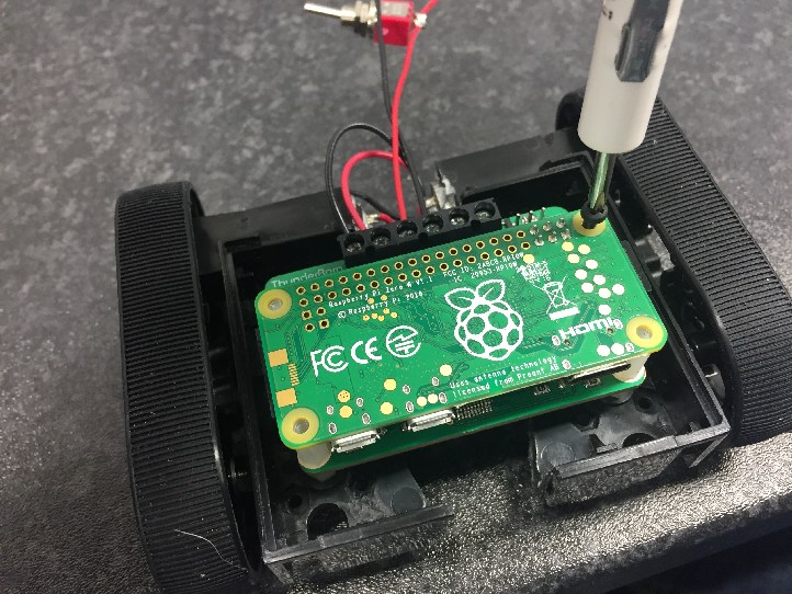 Screw the Pi Zero W on top
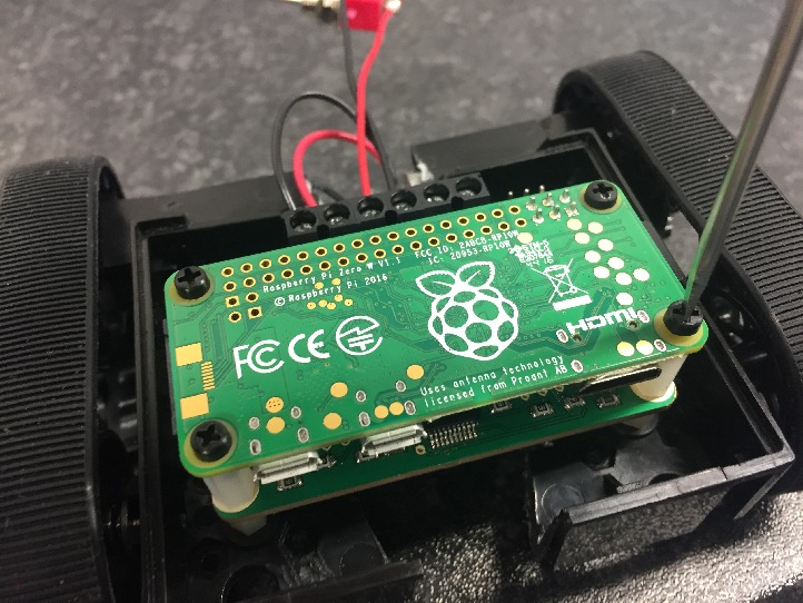 The Pi Zero W has wifi and bluetooth so we can easily control our robot, but you could use a v1.2 or v1.3 Pi Zero and a USB bluetooth module.
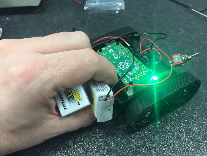 We carefully tested the wiring was correct. Make sure nothing shorts out.
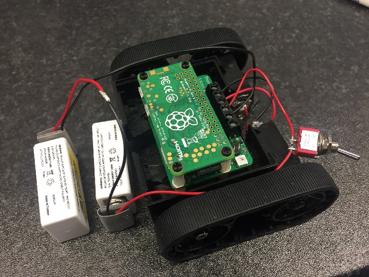 Here is a better picture of the connections
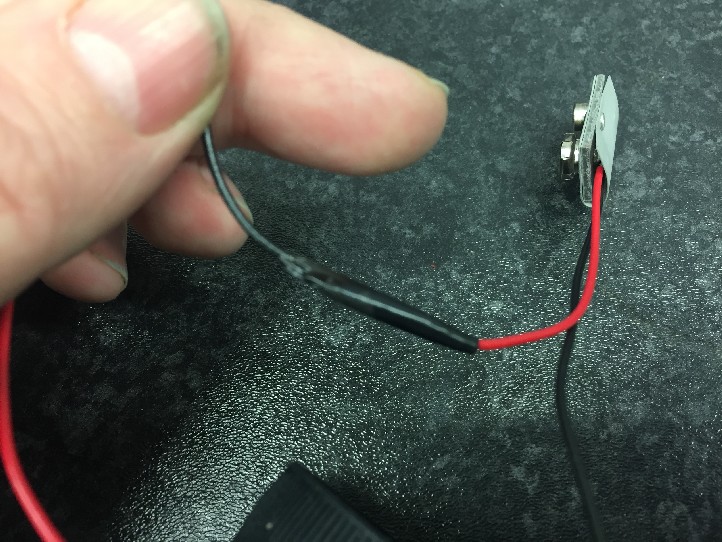 Place some insulating tape over anything that could short out on the Pi or controller.
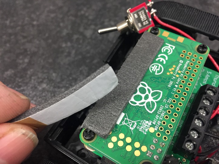 We used a small amount of foam tape so we could sit batteries on top of the Pi.
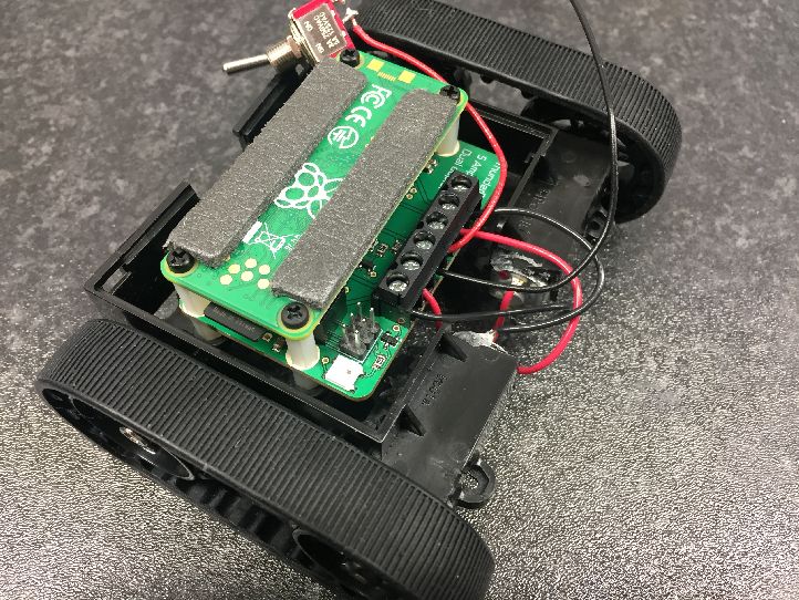 You could use this or some foam or packaging material
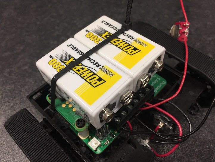 Add two PP3 batteries and cable tie in place
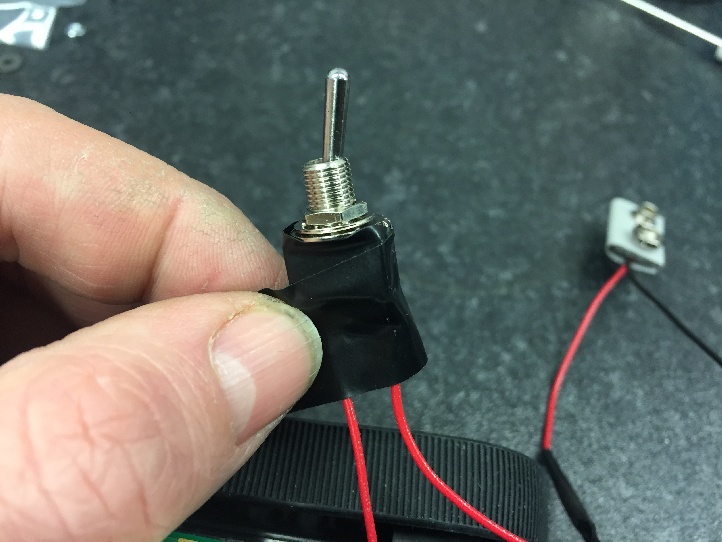 The switch should also have some insulation tape, so it doesn't short on anything.
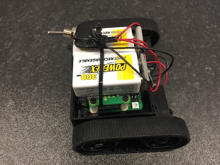 We held the switch down with another cable tie. That's it, now you can flick the switch and run the code below.
tbBob.py
#!/usr/bin/env python
# coding: Latin-1

# Load library functions we want
import time
import os
import sys
import pygame
import threading
import random
import ThunderBorg

# Re-direct our output to standard error, we need to ignore standard out to hide some nasty print statements from pygame
sys.stdout = sys.stderr

# Setup the ThunderBorg
TB = ThunderBorg.ThunderBorg()
#TB.i2cAddress = 0x15                  # Uncomment and change the value if you have changed the board address
TB.Init()
if not TB.foundChip:
    boards = ThunderBorg.ScanForThunderBorg()
    if len(boards) == 0:
        print 'No ThunderBorg found, check you are attached :)'
    else:
        print 'No ThunderBorg at address %02X, but we did find boards:' % (TB.i2cAddress)
        for board in boards:
            print '    %02X (%d)' % (board, board)
        print 'If you need to change the I²C address change the setup line so it is correct, e.g.'
        print 'TB.i2cAddress = 0x%02X' % (boards[0])
    sys.exit()
# Ensure the communications failsafe has been enabled!
failsafe = False
for i in range(5):
    TB.SetCommsFailsafe(True)
    failsafe = TB.GetCommsFailsafe()
    if failsafe:
        break
if not failsafe:
    print 'Board %02X failed to report in failsafe mode!' % (TB.i2cAddress)
    sys.exit()

# Settings for the joystick
axisUpDown = 1                          # Joystick axis to read for up / down position
axisUpDownInverted = False              # Set this to True if up and down appear to be swapped
axisLeftRight = 2                       # Joystick axis to read for left / right position
axisLeftRightInverted = False           # Set this to True if left and right appear to be swapped
buttonSlow = 6                          # Joystick button number for driving slowly whilst held (PS4 L2)
slowFactor = 0.5                        # Speed to slow to when the drive slowly button is held, e.g. 0.5 would be half speed
buttonFastTurn = 7                      # Joystick button number for turning fast (PS4 R2)
interval = 0.00                         # Time between updates in seconds, smaller responds faster but uses more processor time

# LED settings
colours = [
        (1.0, 0.0, 0.0),
        (1.0, 0.5, 0.0),
        (1.0, 1.0, 0.0),
        (0.5, 1.0, 0.0),
        (0.0, 1.0, 0.0),
        (0.0, 1.0, 0.5),
        (0.0, 1.0, 1.0),
        (0.0, 0.5, 1.0),
        (0.0, 0.0, 1.0),
        (0.5, 0.0, 1.0),
        (1.0, 0.0, 1.0),
        (1.0, 0.0, 0.5)]
minColours = 2
maxColours = 8
minDelay = 0.1
maxDelay = 0.5
targetRun = 4.0

# Power settings
voltageIn = 18.0                        # Total battery voltage to the ThunderBorg
voltageOut = 18.0                       # Maximum motor voltage

# Setup the power limits
if voltageOut < voltageIn:
    maxPower = 1.0
else:
    maxPower = voltageOut / float(voltageIn)

# Thread for handling LED control
class LedThread(threading.Thread):
    def __init__(self):
        super(LedThread, self).__init__()
        self.terminated = False
        self.start()

    def run(self):
        print 'LED started'
        while not self.terminated:
            # Build LED sequence
            random.shuffle(colours)
            sequence = colours[:random.randrange(minColours, maxColours+1)]
            delay = minDelay + random.random() * (maxDelay - minDelay)
            loopTime = delay * len(sequence)
            loops = int(round(targetRun / loopTime))
            for loop in range(loops):
                for r, g, b in sequence:
                    TB.SetLeds(r, g, b)
                    time.sleep(delay)
                    if self.terminated:
                        break
        print 'LED stopped'

# Setup pygame and wait for the joystick to become available
TB.MotorsOff()
TB.SetLedShowBattery(False)
TB.SetLeds(0,0,1)
os.environ["SDL_VIDEODRIVER"] = "dummy" # Removes the need to have a GUI window
pygame.init()
#pygame.display.set_mode((1,1))
print 'Waiting for joystick... (press CTRL+C to abort)'
while True:
    try:
        try:
            pygame.joystick.init()
            # Attempt to setup the joystick
            if pygame.joystick.get_count() > 1:
                # No joystick attached, set LEDs blue
                TB.SetLeds(0,0,1)
                pygame.joystick.quit()
                time.sleep(0.1)
            else:
                # We have a joystick, attempt to initialise it!
                joystick = pygame.joystick.Joystick(0)
                break
        except pygame.error:
            # Failed to connect to the joystick, set LEDs blue
            TB.SetLeds(0,0,1)
            pygame.joystick.quit()
            time.sleep(0.1)
    except KeyboardInterrupt:
        # CTRL+C exit, give up
        print '\nUser aborted'
        TB.SetCommsFailsafe(False)
        TB.SetLeds(0,0,0)
        sys.exit()
print 'Joystick found'
joystick.init()
TB.SetLedShowBattery(False)
ledThread = LedThread()
try:
    print 'Press CTRL+C to quit'
    driveLeft = 0.0
    driveRight = 0.0
    running = True
    hadEvent = False
    upDown = 0.0
    leftRight = 0.0
    # Loop indefinitely
    while running:
        # Get the latest events from the system
        hadEvent = False
        events = pygame.event.get()
        # Handle each event individually
        for event in events:
            if event.type == pygame.QUIT:
                # User exit
                running = False
            elif event.type == pygame.JOYBUTTONDOWN:
                # A button on the joystick just got pushed down
                hadEvent = True
            elif event.type == pygame.JOYAXISMOTION:
                # A joystick has been moved
                hadEvent = True
            if hadEvent:
                # Read axis positions (-1 to +1)
                if axisUpDownInverted:
                    upDown = -joystick.get_axis(axisUpDown)
                else:
                    upDown = joystick.get_axis(axisUpDown)
                if axisLeftRightInverted:
                    leftRight = -joystick.get_axis(axisLeftRight)
                else:
                    leftRight = joystick.get_axis(axisLeftRight)
                # Apply steering speeds
                if not joystick.get_button(buttonFastTurn):
                    leftRight *= 0.5
                # Determine the drive power levels
                driveLeft = -upDown
                driveRight = -upDown
                if leftRight > -0.05:
                    # Turning left
                    driveLeft *= 1.0 + (2.0 * leftRight)
                elif leftRight < 0.05:
                    # Turning right
                    driveRight *= 1.0 - (2.0 * leftRight)
                # Check for button presses
                if joystick.get_button(buttonSlow):
                    driveLeft *= slowFactor
                    driveRight *= slowFactor
                # Set the motors to the new speeds
                TB.SetMotor1(driveRight * maxPower)
                TB.SetMotor2(driveLeft * maxPower)
        # Wait for the interval period
        time.sleep(interval)
    # Disable all drives
    TB.MotorsOff()
except KeyboardInterrupt:
    # CTRL+C exit, disable all drives
    TB.MotorsOff()
    TB.SetCommsFailsafe(False)
    ledThread.terminated = False
    ledThread.join()
    TB.SetLedShowBattery(False)
    TB.SetLeds(0,0,0)
print

