PicoBorg - Control small motors from your Raspberry Pi
DC motors, fans and solenoids
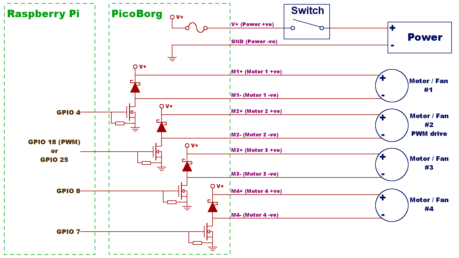
If you are connecting DC motors, these will need to have a stall current less than 2.0A per motor
M1+ M1- {motor 1}
M2+ M2- {motor 2}
M3+ M3- {motor 3}
M4+ M4- {motor 4}
V+ {power supply positive/red}
GND {power supply ground/negative/black}
Stepper motor
The picoBorg is capable of controlling a five or six wire stepper motor in both directions.
To control an eight wire stepper, you can wire the additional two to the remaining M+ connections.
For a standard six wire stepper, the connections are:
| M1+ | Not connected |
| M1- | Stepper Black |
| M2+ | Stepper Yellow (center tap) |
| M2- | Stepper Green |
| M3+ | Stepper White (center tap) |
| M3- | Stepper Red |
| M4+ | Not connected |
| M4- | Stepper Blue |
| V+ | Power supply positive |
| GND | Power supply ground |
This is the centre tap is connected to the power rail, and the end taps are connected to the Mx- connections.
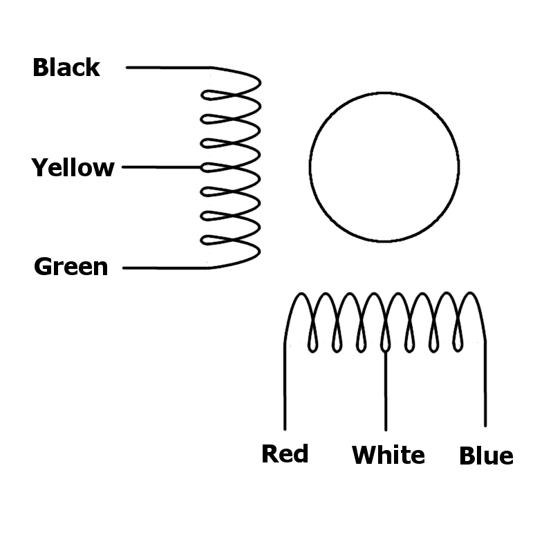
A five wire stepper is the same as a six wire, except there is only a single centre tap.
To choose a stepper motor, first we need to ensure it is six wire, is less than 12V and is rated at less than 2.0A
The one we have chosen here is a 2.7V stepper so we use a 2.7V power source
The Stepper is 1.4A (well less than 2.0A) so should be OK with picoBorg
Some basics
The supply voltage is always available to the motor - the FETs are used to ground the motor.
Keep this in mind when cabling / connecting - that is, if there is power on the V+ connection, there is power on the Mx+ connections!
The diodes are used for Back EMF suppression and this current absorption makes the Diodes hot. Larger inductances or large rotational masses on motors will make the diodes absorb more.
The diode will also add a delay time to the switching as effectively the current is no longer changing as quickly. This may have a significant effect on the speed a relay switches off for example, so keep this in mind for timing calculations.
Soldering
The picoBorg does not have thermal relief on soldering connections and is soldering is difficult as the heat is quickly drawn away from the connection. A powerful iron is required, and we recommend AWG 22 single solid core cable such as DigiKey C2004B-100-ND. If you are not experienced in soldering, we do offer the board with pre flying cables.
Warnings
- There is no thermal shutoff, keep an eye on temperature of the FETs and diodes
- There is no current limiting, you must observe current restrictions
- There is no short circuit or reverse voltage protection
- This is primarily designed to be used with large resistance, low inductance motors and for learning and experimenting purposes. For commercial applications and control of larger motors and lower resistance coils etc, PiBorg or PiBorg nano may be a better solution
- If you are new to electronics and getting started, we recommend you don't use a battery, rather a low current <100mA power supply as this can be more forgiving if you get things wrong
- Be very careful of connections and soldering as mistakes could potentially hurt your picoBorg and Raspberry Pi.
Schematic is available here picoBorg schematic
FETs
The FETs are N channel avalanche rated logic level transistors
VDS = 20 V
RDS approx 0.023 ohms
Max 0.5W dissipation
ID = 2.9A Max at low temp 3.7 Amps
DIODES
The diodes are SS26 Schottky diodes
VRRM Max = 60V (reverse voltage)
IF(AV) = 2A (forward current)
VF max = 700mV (max forward voltage)
IFSM Max >=50A (max surge current)
Diode Datasheet