ZeroBorg - Tiny robot controller for your RPi Zero based robots
Main Examples
Download and installation instructions can be found on the getting started tab, as well as wiring instructions for the motor(s) and power.The package of examples can be downloaded as a zip file directly: http://www.piborg.org/downloads/zeroborg/examples.zip
You can also get the examples and descriptions on the GitHub page: piborg/zeroborg.
ZeroBorg.py
This is the main library for ZeroBorg.It makes life easier by providing simple named functions instead of having to call complicated I²C commands directly, for example:
ZB.SetMotor1(0.5)See the scripts below for examples of use, or the library function listings for usage guidance.
zbStepper.py
This script demonstrates how a stepper motor (4, 5, or 6 wire) can be driven using ZeroBorg.The script will ask you how many steps to move, it will then move that many steps as fast as it can.
Line 16 sets how long the script must remain at a given step before moving to the next position, if the motor is not operating correctly you may need to make this value larger.
Run using:
cd ~/zeroborg./zbStepper.pyzbStepperSequence.py
A simple script which controls two steeper motors automatically based on an example sequence.Lines 168 to 194 determine the sequence the motor will run as a coded operation, this is then looped.
Line 25 sets how long the script must remain at a given step before moving to the next position, if the motor is not operating correctly you may need to make this value larger.
Line 26 tells the script how many degrees are represented by a single step, this will need to be set based on the stepper motor used.
Run using:
cd ~/zeroborg./zbStepperSequence.pyzbJoystick.py and runJoystick.sh
This script uses pygame to demonstrate how we can make a joystick / gamepad control a robotTo run this example you will need to get a joystick / gamepad installed and working with the Raspberry Pi first.
If you are using a PS3 controller our PS3 help page here, otherwise see the JoyBorg, Connecting the joystick to the Raspberry Pi section for guidance.
The script will need to be setup for the controller you are using.
The lines which may need changing are:
- 43:
axisUpDown, the axis index used for speed control - 44:
axisUpDownInverted, set toTrueif the robot drives the wrong way - 45:
axisLeftRight, the axis index used for steering control - 46:
axisLeftRightInverted, set toTrueif the robot turns the wrong way - 47:
buttonResetEpo, the button index used for resetting the safety stop, generally should not be needed - 48:
buttonSlow, the button index used for hold to drive slowly - 49:
slowFactor, the maximum drive speed when the hold to drive slowly button is held - 50:
buttonFastTurn, the button index used for hold to turn fast, allows turning on the spot whilst held
- Left stick up / down: Speed control
- Right stick left / right: Steering control
- L2: Drive slowly whilst held (limits to 50% speed)
- R2: Turn fast whilst held (allows on the spot turning)
- Start button: Resets the safety stop if tripped (indicated by script using the LED)
runJoystick.sh, is only used to hide some irritating lines displayed by pygame, it does not affect how the script works.Run using:
cd ~/zeroborg./runJoystick.shzbMecanumJoy.py and runMecanumJoy.sh

This script uses pygame to demonstrate how we can make a joystick / gamepad control a mecanum wheel based robot, like in our Kickstarter video
To run this example you will need to get a joystick / gamepad installed and working with the Raspberry Pi first.
If you are using a PS3 controller our PS3 help page here, otherwise see the JoyBorg, Connecting the joystick to the Raspberry Pi section for guidance.
The script will need to be setup for the controller you are using.
The lines which may need changing are:
- 44:
axisUpDown, the axis index used for speed control - 45:
axisUpDownInverted, set toTrueif the robot drives the wrong way - 46:
axisLeftRight, the axis index used for strafing control - 47:
axisLeftRightInverted, set toTrueif the robot strafes the wrong way - 48:
axisRotate, the axis index used for spinning control - 49:
axisRotateInverted, set toTrueif the robot spins the wrong way - 50:
buttonResetEpo, the button index used for resetting the safety stop, generally should not be needed - 51:
buttonSlow, the button index used for hold to drive slowly - 52:
slowFactor, the maximum drive speed when the hold to drive slowly button is held
- Left stick up / down: Speed control
- Left stick left / right: Strafing control
- Right stick left / right: Spinning control
- L2: Drive slowly whilst held (limits to 50% speed)
- Start button: Resets the safety stop if tripped (indicated by script using the LED)
runMecanumJoy.sh, is only used to hide some irritating lines displayed by pygame, it does not affect how the script works.Run using:
cd ~/zeroborg./runMecanumJoy.shzbReadAnalog.py
This script demonstrates how you can read the two analogue pins particularly useful for potentiometers (pots).Run using:
cd ~/zeroborg./zbReadAnalog.pyzbReadIR.py
This script demonstrates how you can read the infrared (IR) sensor inputs.These are shown as hexadecimal strings while a button is pressed on the remote control.
Run using:
cd ~/zeroborg./zbReadIR.pyzbIrButtonMap.py and the various zbIrMap*.py files
These scripts store infrared (IR) codes as seen by theZB.GetIrMessage() function.They are not directly used, instead the examples below using remote control use them to decode the button presses.
New codes can be added using the
zbSaveIR.py script explained below.zbRemote.py
This script demonstrates how an infrared (IR) remote can be used to control a robot.The
buttonCommands list contains which button on the remote performs which function.By default a typical Sony or Samsung remote should work like this:
- Power → Shutdown the Raspberry Pi
- Up / 2 → Move forward
- Down / 8 → Move backward
- Left / 4 → Spin left
- Right / 6 → Spin right
New codes added by using the
zbSaveIR.py script can be added to the buttonCommands list.Run using:
cd ~/zeroborg./zbRemote.pyzbSaveIR.py
This script demonstrates how you can save names for the infrared (IR) sensor inputs.It adds new names to the
zbIrButtonMap.py script, which is used by our examples to determine the correct names for the remote buttons.These saved names will be displayed on the ZeroBorg GUI when the corresponding button is held.
Run using:
cd ~/zeroborg./zbSaveIR.pyTo add a new button code do the following:
- Run the script
- Hold the button you wish to name (keep holding), the LED on the ZeroBorg should flicker
- Type the name for this button and press ENTER
- Wait for the script to display the code, then release the button
- Keep repeating from 2 until you have named all of the buttons you want to
- Press ENTER without typing a name to finish
zbRemote.py):If you typed "
red" use Buttons.IR_red.Remember case does matter, we would recommend using all lower case to keep things simple.
If you are using these in your own script add the following line towards the top:
import zbIrButtonMap as ButtonszbGui.py
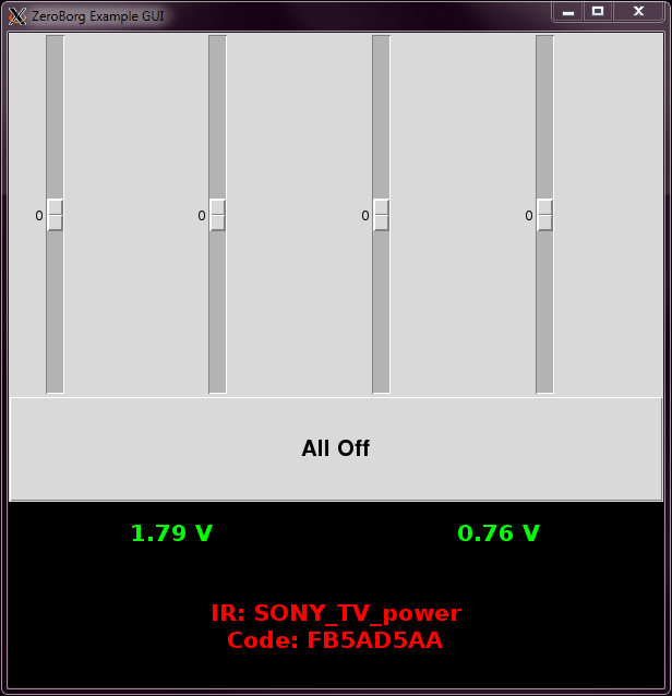
This script shows how you can make a GUI in Python which controls ZeroBorg, as well as providing an easy to use interactive demonstration of the board without needing any additional controller.
Drag the sliders up to make the motor move forwards, down to make the motor move backwards.
To get the same speed as the GUI in a script divide the value shown by 100, e.g. if the GUI shows motor 1 as -35 and you want the same speed run
ZB.SetMotor1(-0.35)in your script.
The "All Off" button will set both motors back to 0, the GUI will also do this when closed.
The values in green are the analog voltage readings, these will be about 0 V with nothing attached.
The values in red are the latest infrared (IR) message status:
- If nothing has been pressed the lines will say "No IR" and "-none-"
- If a button is currently held the top line will say the decoded name, the bottom line will say the raw IR code
- If a button has been released the top line will say "No IR", the bottom line will say the last decoded name
New codes can be added using the zbSaveIR.py script mentioned earlier.
Run using:
cd ~/zeroborg./zbGui.pyor double-clicking the icon on the desktop.
User Examples
Please post any examples you would like to share with others on the forum here.Library Functions
Use by creating an instance of the class, call the Init function, then command as desired, e.g.import ZeroBorg ZB = ZeroBorg.ZeroBorg() ZB.Init() # User code here, use ZB to control the boardMultiple boards can be used when configured with different I²C addresses by creating multiple instances, e.g.
import ZeroBorg
ZB1 = ZeroBorg.ZeroBorg()
ZB2 = ZeroBorg.ZeroBorg()
ZB1.i2cAddress = 0x10
ZB2.i2cAddress = 0x11
ZB1.Init()
ZB2.Init()
# User code here, use ZB1 and ZB2 to control each board separately
For explanations of the functions available call the Help function, e.g.
import ZeroBorg
ZB = ZeroBorg.ZeroBorg()
ZB.Help()
The same help text is also found below
In the below listing any function parameters surrounded by [ ] are optional and may be omitted.
Board Settings
These values should be accessed from a particular instance of the library, and may be set / read differently if more then one is created.Set these after creating an instance but before calling
Init(), for example to set the I²C address:import ZeroBorg ZB = ZeroBorg.ZeroBorg() ZB.i2cAddress = 0x10 ZB.Init()When reading these values to see if things have worked read after calling
Init(), for example to see if the board was found:
import ZeroBorg
ZB = ZeroBorg.ZeroBorg()
ZB.Init()
if ZB.foundChip:
    print 'Yay !'
else:
    print 'Aww...'
busNumber
I²C bus on which the ZeroBorg is attached (Rev 1 is bus0, Rev 2 is bus 1)bus
The smbus object used to talk to the I²C bus, only use this to talk with other I²C devicesi2cAddress
The I²C address of the ZeroBorg chip to controlfoundChip
True if the ZeroBorg chip can be seen, False otherwiseprintFunction
Function reference to call when printing text, ifNone "print" is usedBoard Functions
These represent the majority of the functionality of the ZeroBorg, such as setting motor speedsCall these functions on an instance, after calling
Init(), e.g.import ZeroBorg ZB = ZeroBorg.ZeroBorg() ZB.Init() ZB.SetMotor1(0.4)
Print(message)
Wrapper used by the ZeroBorg instance to print messages, will callprintFunction if set, print otherwiseNoPrint(message)
Does nothing, intended for disabling diagnostic printout by using:ZB = ZeroBorg.ZeroBorg() ZB.printFunction = ZB.NoPrint
Init([tryOtherBus])
Prepare the I²C driver for talking to the ZeroBorgIf
tryOtherBus is True or omitted, this function will attempt to use the other bus if the ZeroBorg devices can not be found on the current busNumberSetMotor1(power)
Sets the drive level for motor 1, from +1 to -1.e.g.
SetMotor1(0) -> motor 1 is stoppedSetMotor1(0.75) -> motor 1 moving forward at 75% powerSetMotor1(-0.5) -> motor 1 moving reverse at 50% powerSetMotor1(1) -> motor 1 moving forward at 100% powerpower = GetMotor1()
Gets the drive level for motor 1, from +1 to -1.e.g.
0 -> motor 1 is stopped0.75 -> motor 1 moving forward at 75% power-0.5 -> motor 1 moving reverse at 50% power1 -> motor 1 moving forward at 100% powerSetMotor2(power)
Sets the drive level for motor 2, from +1 to -1.e.g.
SetMotor2(0) -> motor 2 is stoppedSetMotor2(0.75) -> motor 2 moving forward at 75% powerSetMotor2(-0.5) -> motor 2 moving reverse at 50% powerSetMotor2(1) -> motor 2 moving forward at 100% powerpower = GetMotor2()
Gets the drive level for motor 2, from +1 to -1.e.g.
0 -> motor 2 is stopped0.75 -> motor 2 moving forward at 75% power-0.5 -> motor 2 moving reverse at 50% power1 -> motor 2 moving forward at 100% powerSetMotor3(power)
Sets the drive level for motor 3, from +1 to -1.e.g.
SetMotor3(0) -> motor 3 is stoppedSetMotor3(0.75) -> motor 3 moving forward at 75% powerSetMotor3(-0.5) -> motor 3 moving reverse at 50% powerSetMotor3(1) -> motor 3 moving forward at 100% powerpower = GetMotor3()
Gets the drive level for motor 3, from +1 to -1.e.g.
0 -> motor 3 is stopped0.75 -> motor 3 moving forward at 75% power-0.5 -> motor 3 moving reverse at 50% power1 -> motor 3 moving forward at 100% powerSetMotor4(power)
Sets the drive level for motor 4, from +1 to -1.e.g.
SetMotor4(0) -> motor 4 is stoppedSetMotor4(0.75) -> motor 4 moving forward at 75% powerSetMotor4(-0.5) -> motor 4 moving reverse at 50% powerSetMotor4(1) -> motor 4 moving forward at 100% powerpower = GetMotor4()
Gets the drive level for motor 4, from +1 to -1.e.g.
0 -> motor 4 is stopped0.75 -> motor 4 moving forward at 75% power-0.5 -> motor 4 moving reverse at 50% power1 -> motor 4 moving forward at 100% powerSetMotors(power)
Sets the drive level for all motors, from +1 to -1.e.g.
SetMotors(0) -> all motors are stoppedSetMotors(0.75) -> all motors moving forward at 75% powerSetMotors(-0.5) -> all motors moving reverse at 50% powerSetMotors(1) -> all motors moving forward at 100% powerMotorsOff()
Sets all motors to stopped, useful when ending a programSetLed(state)
Sets the current state of the LED,False for off, True for onstate = GetLed()
Reads the current state of the LED,False for off, True for onResetEpo()
Resets the EPO latch state, use to allow movement again after the EPO has been trippedstate = GetEpo()
Reads the system EPO latch state.If
False the EPO has not been tripped, and movement is allowed.If
True the EPO has been tripped, movement is disabled if the EPO is not ignored (see SetEpoIgnore)Movement can be re-enabled by calling
ResetEpo.SetEpoIgnore(state)
Sets the system to ignore or use the EPO latch, set toFalse if you have an EPO switch, True if you do notstate = GetEpoIgnore()
Reads the system EPO ignore state,False for using the EPO latch, True for ignoring the EPO latchstate = HasNewIrMessage()
Reads the new IR message received flag.If
False there has been no messages to the IR sensor since the last read.If
True there has been a new IR message which can be read using GetIrMessage().message = GetIrMessage()
Reads the last IR message which has been received and clears the new IR message received flag.Returns the bytes from the remote control as a hexadecimal string, e.g.
'F75AD5AA8000'Use
HasNewIrMessage() to see if there has been a new IR message since the last call.SetLedIr(state)
Sets if IR messages control the state of the LED,False for no effect, True for incoming messages blink the LED.state = GetLedIr()
Reads if IR messages control the state of the LED,False for no effect, True for incoming messages blink the LED.voltage = GetAnalog1()
Reads the current analog level from port #1 (pin 2).Returns the value as a voltage based on the 3.3 V reference pin (pin 1).
voltage = GetAnalog2()
Reads the current analog level from port #2 (pin 4).Returns the value as a voltage based on the 3.3 V reference pin (pin 1).
SetCommsFailsafe(state)
Sets the system to enable or disable the communications failsafeThe failsafe will turn the motors off unless it is commanded at least once every 1/4 of a second
Set to
True to enable this failsafe, set to False to disable this failsafeThe failsafe is disabled at power on
state = GetCommsFailsafe()
Read the current system state of the communications failsafe,True for enabled, False for disabledThe failsafe will turn the motors off unless it is commanded at least once every 1/4 of a second
Help()
Displays the names and descriptions of the various functions and settings providedThis will be the same text as above
Utility Functions
These functions are mostly used for setting up boards, they can be used to change I²C addresses to new values to either avoid conflicts with other devices or allow multiple ZeroBorgs to be used by a single Raspberry Pi.Call these functions directly from the module, e.g.
import ZeroBorg
ZeroBorg.ScanForZeroBorg()
ScanForZeroBorg([busNumber])
Scans the I²C bus for a ZeroBorg boards and returns a list of all usable addressesThe
busNumber if supplied is which I²C bus to scan, 0 for Rev 1 boards, 1 for Rev 2 boards, if not supplied the default is 1SetNewAddress(newAddress, [oldAddress], [busNumber])
Scans the I²C bus for the first ZeroBorg and sets it to a new I²C addressIf
oldAddress is supplied it will change the address of the board at that address rather than scanning the busThe
busNumber if supplied is which I²C bus to scan, 0 for Rev 1 boards, 1 for Rev 2 boards, if not supplied the default is 1Warning, this new I²C address will still be used after resetting the power on the device


