
Installation Issues

Forums:
Post here for queries regarding setup problems.
We recommend you try using the troubleshooting instructions here first if you have not already.
Please try to list as much about the problem as you can (OS distribution, versions, motor setup et cetera), the more we know the easier it is to help :)
- Log in to post comments

benrogers
Sat, 11/19/2016 - 18:46
Permalink
no module named 'ZeroBorg'
Hi - I think I've installed properly - the GUI controller works - but when I try to import ZeroBorg in python, I get no module named ZeroBorg. WHat step have I missed?
I used a fresh install of raspbian.
Thanks,
Ben
benrogers
Sat, 11/19/2016 - 21:10
Permalink
solved
I needed my python code to be in the zeroborg folder. :)
piborg
Mon, 11/21/2016 - 10:41
Permalink
Glad you have it sorted :)
As you have found out, the error simply means that Python does not know where to find the
ZeroBorg.pyfile.There are three main ways around this problem:
~/zeroborgdirectory.This is what we would normally suggest as well.
ZeroBorg.pyscript into the directory you are using.This is best when you want to share your scripts with others.
This makes life easier, but requires adding a couple of lines to each script:
import sys sys.ptah.append('/home/pi/zeroborg') import ZeroBorgjanemcclung88@g...
Sat, 11/26/2016 - 15:10
Permalink
Zeroborg not powering to connector
Hi,
I have connected a 9v battery to V+ and GND connectors and can confirm the 9v is available across the switch. When I check the voltage at the 6 pin connector to which the pi zero would connect I do not get any voltage. Is there something additional on the board other than the 2 jumpers across the switch which would cause this, I have the jumpers set as per the Getting Started section,
Thanks Jane
piborg
Sat, 11/26/2016 - 19:12
Permalink
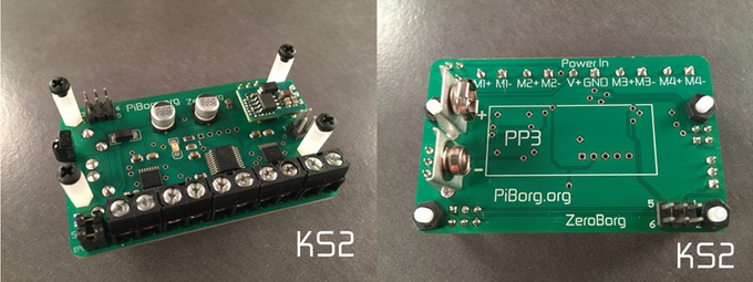
ZeroBorg KS1 or KS2?
Which model of ZeroBorg do you have?
If you have a KS2 then it should be providing 5V power to the 6-pin connectors with the two jumpers fitted:
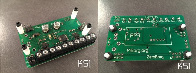
If you have a KS1 then the ZeroBorg does not provide the 5V power, instead it expects it to be supplied to the Raspberry Pi from another device:
janemcclung88@g...
Sat, 11/26/2016 - 19:51
Permalink
Thank you for responding so
Thank you for responding so quickly.
That would explain my problem I have a KS1 I believe I should have a KS2, really appreciate your guidance and the quick turnaround saved me from excessive headbanging :)
Jane
johnfking@tisca...
Wed, 11/30/2016 - 17:35
Permalink
ZeroBorg KS1
Is it ok to add the 5v regulator to the KS1 and if so do I need to alter any links?
piborg
Wed, 11/30/2016 - 17:57
Permalink
Adding DC/DC to a ZeroBorg KS1
Yes, you can solder in a 5V DC/DC regulator into the set of three holes on a ZeroBorg KS1 to add the ability to power a Raspberry Pi.
You do not need to solder or modify any other part of the board.
Make sure the DC/DC is fitted the same way as shown on the KS2, if fitted wrong it can cause damage.
johnfking@tisca...
Thu, 12/01/2016 - 15:26
Permalink
Adding DC/DC to a ZeroBorg KS1
Thanks for your help, all worked fine when I realised the + and - holes on the board are for mounting and not connected. Now connected battery wires to screw connectors!
tom.s.meyer@gma...
Sat, 04/29/2017 - 21:08
Permalink
installation of DCDC converter
Ordered the KS1 before I realized that I would need the DC/DC converter. Ordered the 9V to 5V DCDC converter and have installed it on the Piborg Zero. Also installed the 9V battery terminals and installed them as well. (See pictures) There are no solder drips or bad connections. I have 9V on the power terminal, so I know that at least the Piborg Zero is getting power.
I am not getting any voltage into or out of the converter. Since there is not an installation video I went off of the pictures on of the KS2/KS3.
So, is there a jumper that must be connected? Did I miss something?
Thanks for the help,
Tom
piborg
Sat, 04/29/2017 - 22:26
Permalink
Battery connection is not soldered
Looking closely it seems like the connection between the battery and the fuse is not soldered. From how it looks this might not be making any connection at all. If so this would explain the problem.
I have attached an image with the tab in question circled. We would recommend soldering all three tabs on both of the 9V terminals for added stability anyway. With only one soldered you run the risk of braking the terminals off if your robot collides with something.
tom.s.meyer@gma...
Sat, 04/29/2017 - 22:34
Permalink
Thanks for your fast reply.
Thanks for your fast reply. It's soldered from the top. All pins are soldered. I believe that this must be connected as there is 9V on the power pins as shown in the 3rd picture.
piborg
Sun, 04/30/2017 - 08:36
Permalink
Power issue
The connection from that fuse is the one that eventually gets to the DC/DC pin. It is possible one of the components is not making a good connection.
If you could measure the voltage between the GND terminal and each of these points:
Points labelled in the image below.
If everything is working normally these should all read the same as the battery voltage.
tom.s.meyer@gma...
Sat, 05/06/2017 - 22:16
Permalink
power
Ok, well, had 9.4V at each of the locations. Still no 5V out.
Dabbed a bit more solder on the pin and voila! 5V out of the converter!
Thanks for the help and the awesome diagnostic drawings!
PauloK
Sun, 01/14/2018 - 08:21
Permalink
Raspberry Pi resetting when motors kick in
Hi,
I have an issue with power supply for raspberry pi (using ZeroBorg KS2 with DC/DC).
Rasperry pi is booting normally, but after initialize of ZeroBorg and first power on of the motors raspberry pi is rebooting unexpected.
My setup:
- power supply from 6 AA NiMh accus to ZeroBorg
- raspberry pi directly connected to ZeroBorg
- 4 motors
- 7,8V measured on input
- 4,9V measured on the power supply of raspberry pi
Can you give me some hint what might be an issue here?
piborg
Sun, 01/14/2018 - 11:52
Permalink
Not enough power
It sounds like the current needed by the four motors and the DC/DC at the same time is probably too much for the 6x AAs to handle.
When the batteries cannot keep up with the current demand they produce a lower voltage to compensate. In this case the necessary current is large enough that it is causing the batteries to get below 7 V, causing the DC/DC to turn off.
The exact current required depends on the motors themselves, but it is likely that they need a larger current to start them moving than they will need to keep moving. This would mean the power dip is temporary, but still long enough to loose the 5V output and cause the Pi to reset.
I would suggest moving to 8x AAs, this will allow the battery voltage to dip a long way before causing the reset issue. This should stop the Pi resetting :)
PauloK
Mon, 01/15/2018 - 13:55
Permalink
OK, thanks for the prompt
OK, thanks for the prompt feedback. I will give it a try with 8xAA. I was worried it might be too much for ZeroBorg and agraid to fry it. I'll let you know if it worked out.
piborg
Mon, 01/15/2018 - 14:19
Permalink
Voltage limits
When the batteries are fully charged it will be very close to the 10.8 V limit, but still within:
duckstar
Wed, 03/07/2018 - 13:09
Permalink
Turns right faster than turns left
Hi
I have installed the default code and added a controller and for some reason it turns faster one way than the other. What is likely to cause this?
Thanks
Nic
piborg
Wed, 03/07/2018 - 21:18
Permalink
Slight difference between positive and negative power
On the ZeroBorg this is a slight difference in power values between running motors with positive power and negative power. Put simply the motors run slightly faster in one direction than the other.
You can solve the turning difference by adjusting the code so that all the motors use the same direction for driving forwards.
First open
zbJoystick.pyin an editor and look for these lines:# Set the motors to the new speeds ZB.SetMotor1(-driveLeft * maxPower) ZB.SetMotor2(-driveLeft * maxPower) ZB.SetMotor3(driveRight * maxPower) ZB.SetMotor4(driveRight * maxPower)What you need to do is add a
-sign in front of thedriveRightvalues, like this:# Set the motors to the new speeds ZB.SetMotor1(-driveLeft * maxPower) ZB.SetMotor2(-driveLeft * maxPower) ZB.SetMotor3(-driveRight * maxPower) ZB.SetMotor4(-driveRight * maxPower)Once you have changed the code swap the + and - connections on motors 3 and 4 on the ZeroBorg.
This will make them move in the correct direction again.
danergis
Thu, 01/14/2021 - 22:34
Permalink
Hi PiBorg,
Hi PiBorg,
I'm having trouble getting the Raspberry Pi Zero W to communicate with the ZeroBorg complete. The board is currently soldered to the Pi with pin continuity. I followed the troubleshooting pages and done various checks (see attached screenshots) but still no joy - any suggestion what else I can check?
Thanks
Dan
piborg
Fri, 01/15/2021 - 11:31
Permalink
I2C problems
It looks like you have already checked for the likely causes. Unfortunately this probably means that the I2C on one of the boards is not working :(
The first thing to try is installing the ZeroBorg software again on a completely fresh install of Raspbian. We have seen this fix I2C problems for people occasionally when we could not identify the cause.
If that does not help then you can test the I2C pins on the Pi. To do this you will need to disconnect it from the ZeroBorg and power it using the USB connector.
Next download and build the WiringPi code:
After it has built run the GPIO pin tester:
You should see some diagnostics after pressing ENTER:
PinTest
=======

This is a simple utility to test the GPIO pins on your Raspberry Pi.

NOTE: All GPIO peripherals must be removed to perform this test. This
  includes serial, I2C and SPI connections. You may get incorrect results
  if something is connected and it interferes with the test.

This test can only test the input side of things. It uses the internal
pull-up and pull-down resistors to simulate inputs. It does not test
the output drivers.

You will need to reboot your Pi after this test if you wish to use the
serial port as it will be left in GPIO mode rather than serial mode.

This test only tests the original pins present on the Rev A and B. It
does not test the extra pins on the Revision A2, B2 nor the A+ or B+

Please make sure everything is removed and press the ENTER key to continue,
or Control-C to abort...

          The main 8 GPIO pins  0: 7:  OK
                The 5 SPI pins 10:14:  OK
               The serial pins 15:16:  OK
                  The I2C pins  8: 9:  OK
Hopefully all of the end lines say
OK, otherwise the GPIO is not working correctly on the Raspberry Pi itself.After the test restart the Raspberry Pi to reset the GPIO pins back to their standard behaviour.
If either of the I2C pins fail this test then the problem is with the Pi. If they pass then the ZeroBorg is probably faulty and we will need to send you a replacement.
danergis
Fri, 01/15/2021 - 21:19
Permalink
Hi PiBorg,
Hi PiBorg,
Thanks for the quick response!
I tried the test on the Raspberry Pi Zero W and another zero W too. I also connected the board up to 3B+ via a breadboard. The OS was reinstall on to a spare microSD card and the ZeroBorg software reinstall too but still no joy.
What is the best way of organising an exchange?
Thanks
Dan
piborg
Sun, 01/17/2021 - 15:26
Permalink
Replacement ZeroBorg
The best thing to do is fill in our contact form so that we can get the address to ship the replacement board to.
Fill in our contact form here.
We will then get a replacement sent out to you in the next couple of days :)
danergis
Thu, 01/21/2021 - 21:02
Permalink
Glad to report the
Glad to report the replacement is working perfectly. Thanks for your support!
ruairi15fagan
Sun, 04/25/2021 - 14:00
Permalink
Python Version
What version of python is this the print statements dont make sense to me. My raspberry pi creates errors for all of the print statements. Also I keep getting the error "self.bus = smbus.SMBus(self.busNumber)"
piborg
Sun, 04/25/2021 - 16:56
Permalink
Python 2
The ZeroBorg example scripts are written to run on Python 2. This is the version of python that should be loaded if you run the
pythoncommand in a terminal on the Raspberry Pi.It sounds like you have an old version of the ZeroBorg scripts, we moved away from using the smbus module quite a while ago.
The latest version of the example scripts can be downloaded here: http://www.piborg.org/downloads/zeroborg/examples.zip
If you need a Python 3 version of the ZeroBorg.py script there is one available here: ZeroBorg library for Python 3
ruairi15fagan
Mon, 04/26/2021 - 09:58
Permalink
Thanks a lot got it running
Thanks a lot got it running with python3 version now however I am getting an error as it is not detecting my board saying "Missing ZeroBorg at bus 40"
piborg
Mon, 04/26/2021 - 12:40
Permalink
Missing ZeroBorg
What result do you get from running this command:
sudo i2cdetect -y 1ruairi15fagan
Mon, 04/26/2021 - 13:03
Permalink
it returns the table with
it returns the table with minuses at every point.
ruairi15fagan
Mon, 04/26/2021 - 13:05
Permalink
no device is detected at any
no device is detected at any of the locations. Apologies for the duplicate comments
piborg
Mon, 04/26/2021 - 14:19
Permalink
Missing ZeroBorg
It may be that the ZeroBorg is not powered, or that the Raspberry Pi is unable to talk to the ZeroBorg.
If you could answer some questions it will help me diagnose what the problem is for you:
Photos of the connections might be helpful here.
ruairi15fagan
Mon, 04/26/2021 - 17:12
Permalink
I'm powering the zeroborg
I'm powering the zeroborg with 6 9V batteries wired in parrallel and the raspberry pi is powered off of the zeroborg. All 6 gpio pins are connected as shown in the getting started section and raspberry pi is running fine. Tried switching cables to no avail. Is it possible my i2c pins are dodgy or is there any mistakes I could have made in setting up i2c
piborg
Tue, 04/27/2021 - 10:03
Permalink
I2C connections - checking the Pi I2C pins
If the Pi is powering from the ZeroBorg then the problem is most likely to be with the I2C connections themselves.
It is possible that the I2C pins are faulty, but it is more likely that the cables are not making a good enough connection - the I2C is more sensitive to the quality of the connection then the power is.
You can test the I2C pins on the Pi to make sure they are not the problem. To do this you will need to disconnect it from the ZeroBorg and power it using the USB connector.
Next download and build the WiringPi code:
After it has built run the GPIO pin tester:
You should see some diagnostics after pressing ENTER:
PinTest
=======

This is a simple utility to test the GPIO pins on your Raspberry Pi.

NOTE: All GPIO peripherals must be removed to perform this test. This
  includes serial, I2C and SPI connections. You may get incorrect results
  if something is connected and it interferes with the test.

This test can only test the input side of things. It uses the internal
pull-up and pull-down resistors to simulate inputs. It does not test
the output drivers.

You will need to reboot your Pi after this test if you wish to use the
serial port as it will be left in GPIO mode rather than serial mode.

This test only tests the original pins present on the Rev A and B. It
does not test the extra pins on the Revision A2, B2 nor the A+ or B+

Please make sure everything is removed and press the ENTER key to continue,
or Control-C to abort...

          The main 8 GPIO pins  0: 7:  OK
                The 5 SPI pins 10:14:  OK
               The serial pins 15:16:  OK
                  The I2C pins  8: 9:  OK
Hopefully all of the end lines say
OK, otherwise the GPIO is not working correctly on the Raspberry Pi itself.After the test restart the Raspberry Pi to reset the GPIO pins back to their standard behaviour.
If either of the I2C pins fail this test then the problem is with the Pi. If they pass then the problem is either with the cables or the ZeroBorg itself.
ruairi15fagan
Tue, 04/27/2021 - 17:26
Permalink
Tested it with different
Tested it with different version of pin tester as that one failed to download. Results are as seen below none of the failed pins are required for zeroborg however so I dont believe thats the issue. I was testing last night and I dont know why but it detected the zeroborg and ran for about three hours. Now no longer works again. Very confused. Could I have done something to break it while trying to get my script running on boot.My script is also linked below and I am running python3.
# Load library functions we want import time import os import ZeroBorg3 as ZeroBorg from firebase_admin import credentials from firebase_admin import firestore #====================================================================== # Reading single character by forcing stdin to raw mode import sys import tty import termios cred = credentials.Certificate("firebase-sdk.json") firebase_admin.initialize_app(cred) db = firestore.client() #firestore access users_db = db.collection("users").stream() for doc in users_db: print("\n\nuser: {} \n\ndata: {} ".format(doc.id, doc.to_dict())) print("\n\nuser: {} \n\ndata: {} ".format(doc.id, doc.to_dict()["username"])) # Setup the ZeroBorg ZB = ZeroBorg.ZeroBorg() #ZB.i2cAddress = 0x40 # Uncomment and change the value if you have changed the board address ZB.Init() if not ZB.foundChip: boards = ZeroBorg.ScanForZeroBorg() if len(boards) == 0: print('No ZeroBorg found, check you are attached :)') else: print('No ZeroBorg at address %02X, but we did find boards:' % (ZB.i2cAddress)) for board in boards: print(' %02X (%d)' % (board, board)) print('If you need to change the I²C address change the setup line so it is correct, e.g.') print('ZB.i2cAddress = 0x%02X' % (boards[0])) sys.exit() #ZB.SetEpoIgnore(True) # Uncomment to disable EPO latch, needed if you do not have a switch / jumper ZB.SetCommsFailsafe(False) ZB.ResetEpo() # Power settings voltageIn = 9.0 # Total battery voltage to the ZeroBorg (change to 9V if using a non-rechargeable battery) voltageOut = 6.0 # Maximum motor voltage # Setup the power limits if voltageOut > voltageIn: maxPower = 1.0 else: maxPower = voltageOut / float(voltageIn) def car_forward(): ZB.SetMotor1(1 * maxPower)#back left ZB.SetMotor4(-1 * maxPower)#back right ZB.SetMotor2(-1 * maxPower)#front left ZB.SetMotor3(1 * maxPower)#front right time.sleep(0.5) ZB.SetMotor1(0) ZB.SetMotor4(0) ZB.SetMotor2(0) ZB.SetMotor3(0) def car_back(): ZB.SetMotor1(-1 * maxPower) ZB.SetMotor4(1 * maxPower) ZB.SetMotor2(1 * maxPower) ZB.SetMotor3(-1 * maxPower) time.sleep(0.5) ZB.SetMotor1(0) ZB.SetMotor4(0) ZB.SetMotor2(0) ZB.SetMotor3(0) def car_left(): ZB.SetMotor1(1 * maxPower) ZB.SetMotor4(1 * maxPower) ZB.SetMotor2(-1 * maxPower) ZB.SetMotor3(-1 * maxPower) time.sleep(0.5) ZB.SetMotor1(0) ZB.SetMotor4(0) ZB.SetMotor2(0) ZB.SetMotor3(0) def car_right(): ZB.SetMotor1(-1 * maxPower) ZB.SetMotor4(-1 * maxPower) ZB.SetMotor2(1 * maxPower) ZB.SetMotor3(1 * maxPower) time.sleep(0.5) ZB.SetMotor1(0) ZB.SetMotor4(0) ZB.SetMotor2(0) ZB.SetMotor3(0) def on_snapshot(doc_snapshot, changes, read_time): for doc in doc_snapshot: print(u'Received document snapshot: {}'.format(doc.id)) if doc_ref.get().to_dict()["executed"] == "False": if doc_ref.get().to_dict()["action"] == "Forward": car_forward() elif doc_ref.get().to_dict()["action"] == "Backward": car_back() elif doc_ref.get().to_dict()["action"] == "Left": car_left() else: car_right() doc_ref.set({u"action":u"Null", u"executed":u"True"}) doc_ref = db.collection('current_actions').document('current_actions') doc_watch = doc_ref.on_snapshot(on_snapshot) # Keep the app running while True: time.sleep(1) print('processing...')piborg
Wed, 04/28/2021 - 16:05
Permalink
Sometimes working
Sorry about the old link, I forgot that site is no longer available :(
The good news is that the problem is not in your script, nothing it is doing could cause this issue :)
The fact you see GPIO faults on other pins is interesting - do you have devices other than the ZeroBorg attached to your Raspberry Pi?
If you do not have anything else attached then I think there are two likely candidates to explain the issue:
ruairi15fagan
Sun, 05/02/2021 - 12:49
Permalink
Thanks very much. Not sure
Thanks very much. Not sure what the issue was to be honest. I restarted with a new install of noobs and it is now working perfectly. The Zeroborg is an excellent board and youve been incredibly helpful
ruairi15fagan
Sun, 05/02/2021 - 12:49
Permalink
:)
:)