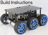
About PicoBorg Reverse usage and documentation
Forums:
Dear all,
I've built the DiddyBorg robot and it works really good.
But I should say there there is something that I would like to undestand better about the connection with the PicoBorg Reverse board: I would love to keep separated the two power supplies (one for the BattBorg-Raspberry and the other for the PicoBorg Reverse).
In particulary in yours "build instructions" there are:
-connection between battery and BattBorg
-shortcut (with wires) between the input power supply of BattBorg and PicoBorg Reverse
-the BattBorg is connected with headers on the PicoBorg Reverse.
From the yours documentation I can understand that the two boards can work separately with 7-36V as power supply.
Who is generating the 5 voltage? I think the BattBorg. But how the PicoBorg can influence the supply of 5V for raspberry? How can I keep separated the two boards? Will raspberry and PicoBorg continue to "speak" without problems? Is it perfectly compatible? Raspberry take only the 5 voltage to generate the 3.3 V or this voltage is even generated by other boards?
The goal should be to connect just GND, SCL and SDA for the instructions (Raspberry-PicoBorg Reverse) and the GND - 5V for the supply (Raspberry-BattBorg).
Some documentation or some useful link can be appreciated.
Thank you so much,
Leo
- Log in to post comments


piborg
Sat, 01/10/2015 - 00:27
Permalink
Separate power supplies for DiddyBorg
The BattBorg generates the 5v used by the Raspberry Pi from the battery connected between its V+ and GND screw terminals.
The Raspberry Pi generates the 3.3v from the 5v.
The PicoBorg Reverse uses the 3.3v for powering the on board logic, but this is only responsible for communication with the Raspberry Pi.
The motor outputs are powered from the battery connected between the V+ and GND screw terminals on the PicoBorg Reverse.
If you have two separate battery packs then you can connect them as follows:
There should be no connections between the BattBorg and PicoBorg Reverse V+ / GND when used like this.
All the required connections for communication between the Raspberry Pi and the PicoBorg Reverse are in the six-pin header.
This means the communications will still work reliably even with two separate battery packs.
leonardo.surian...
Sat, 01/10/2015 - 16:57
Permalink
About the schematic of PicoBorg Reverse
Thank you so much. Everything is clear.
The question now is: why the BattBorg is connected to the PicoBorg Reverse? What do the BattBorg pass to the PicoBorg Reverse? (in addiction to the 5v of rasp). Is it possible to have the schematic of the project or something like a "block diagram" of the PicoBorg Reverse? What I want to do is to undestand if Leaving all the connections as is shown in the project, can the currents of motors influence the raspberry power supply? ....I say this because sometime the system stops working and I should reboot.
piborg
Sat, 01/10/2015 - 18:37
Permalink
BattBorg connected to PicoBorg Reverse
The reason for attaching the BattBorg to the PicoBorg Reverse is that the provided connection cables would need to be attached to the same GPIO pins.
By connecting the BattBorg to the PicoBorg Reverse instead it removes the need to use splitter cables or a board which duplicates the GPIO pins (such as TriBorg).
In the standard setup it is possible that when the batteries are getting flat that the motors can cause a sudden drain on the battery which is enough to temporarily drop the voltage below what the BattBorg requires to generate the 5v.
This should not happen if two separate battery packs are used for each board.
Is there any particular event which seems to cause the system to stop working?
leonardo.surian...
Mon, 01/12/2015 - 10:27
Permalink
about the system stop working
It seems that there are no reason. I think it could be something related with Raspian OS. It is possible to see that the whole system is slowed down sometime....I've tryed to see the CPU working but there are no somuch work on that. In next days I will try to investigate more on this and if you are curious I will let you know.
Again the only question now is: is there a schematic (or box diagram) about the PicoBorg Reverse? Thank you so much for your support,
cheers, Leo
piborg
Mon, 01/12/2015 - 17:46
Permalink
PicoBorg Reverse schematic
I forgot about that bit...
I have attached the schematic for the board as a PDF file.
I hope you find out what the problem causing the Raspberry Pi to misbehave actually is.
rburg
Sat, 12/03/2016 - 08:40
Permalink
USB powerbank
I have a similar question. Rather than connect the 5v supply for pi to bsttborg can I just use a USB powerbank and plug it into the Pi. Does this mean I should just disconnect or remove battborg?
Thanks.
piborg
Sat, 12/03/2016 - 19:03
Permalink
Yes, you can use a powerbank instead of the BattBorg
Yes, powering the PicoBorg Reverse from batteries and using a USB powerbank to power the Raspberry Pi will work correctly.
Since powering the Raspberry Pi and the USB connector at the same time is not a good idea we would recommend removing the BattBorg entirely first.
rburg
Sun, 12/04/2016 - 00:32
Permalink
Excellent. Thanks v much for
Excellent. Thanks v much for the prompt reply.
rburg
Mon, 12/05/2016 - 20:55
Permalink
Big difference
This works really well and makes a big difference. I was getting regular wifi drops possibly due to the current drain from the motors affecting the wifi dongle. Anyway, it's now rock steady running the pi off a lipo powerbank.
Thanks