Separate power supplies for complex setup
Forums:
Hi,
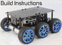
I recently built my DiddyBorg and added an UltraBorg with the 4 distance sensors and 2 servos to it.
In addition, I have a Pi Camera and a large number of sensors that I connected to the Pi.
Apparently this was a bit too much for the power supply chain - as soon as I connected everything and powered up the bot, I noticed that the red PWR LED of the Pi was completely off (although the Pi still worked and got readings from all sensors).
I disconnected all sensors (except the ones connected to the UltraBorg) and everything looked normal again.
This made me start to investigate what options do I have to use 2 power supplies (ideally a power bank only for the Pi and the sensors connected directly to it, and the 12V pack for the rest).
I stumbled across this - however, the setup there is simpler than mine and the provided answer doesn't answer all the questions that I have right now.
Thus, I'd like to suggest the following setup that I have in mind to solve my issue, along with some final questions in relation to the problem.
Hopefully these will also help others.
---
The setup I have in mind:
B1 = 7.4V, 2-cell LiIon
B2 = 12V, 10-cell NiMH
RPi = Raspberry Pi 2
PbRev = PicoBorg Reverse
Ub = Ultraborg
Bb = BattBorg
A. Power Supply 1
- Connect B1 to GND and V+ of Bb
- Connect the Bb on top of one of the 6-pin connectors of the Ub (as in the default configuration, but instead of the PbRev we have the Ub)
- Connect the other 6-pin connector of the Ub to the RPi
--- The RPi gets its 5V from the Ub which in turn gets it from the Bb, which gets 7.4V from B1. ---
--- The Ub gets 3V for the logic and SDA/SCL directly from RPi. ---
B. Power Supply 2
- Connect B2 to GND and V+ of PbRev
- Connect *ONLY* the PbRev's SDA, SCL, 3.3V and GND to the RPi for data communication (so only pins 1, 3, 5, 6 - no 5V!), since the RPi is already powered by the Bb through the Ub, and the PbRev provides its own 5V (from B2), but not its 3.3V for the logic.
--- The PbRev gets its 12V from B2. ---
--- The PbRev communicates to the RPi via I2C / 3.3V connection. ---
--- When using 2 batteries, we need to have a common GND line in between them. ---
--- This leaves me with a free 6-pin connector on the PbRev for other I2C sensors / purposes. ---
---
My questions:
- Is it possible to connect the Bb on top of the Ub as described at A.2. above?
- Does the PbRev need an external 5V supply, or does it generate it itself from the 12V input voltage (B2)?
- The PbRev *NEEDS* an external 3.3V from the RPi to power its logic - is that correct?
- If using 2 batteries, is it safe to have a common GND line?
- If my assumptions above are wrong, what is the solution to achieve the above results (but please explain in a bit more detail than in the comment I mentioned, if possible)?
- What is the best recipe for using 2 power supplies, 1 Bb, 1 PbRev and 1 Ub?
- Ultimately, is it possible to power (only) the RPi from a power bank via the micro-USB connector, and the rest from the provided 12V pack?
---
Thank you and sorry for the wall of text and avalanche of questions!
- Log in to post comments


piborg
Fri, 01/15/2016 - 12:01
Permalink
Separate power supplies for complex setup
It can be tricky figuring out how two different batteries work in a single robot, I think you have a well thought out plan here.
In answer to your questions:
The connections are only there to allow another board using the daisy-chain connection to get to the 5V from the GPIO
If you need 5V for any devices connected to the PicoBorg Reverse they will need to have it supplied by another board
This is to ensure that all of the I2C levels are the same and avoid errors
It is perfectly fine to have the GNDs common in this case, and in most cases
Given you are trying to isolate the supply to the Raspberry Pi I would say to see my answer to question 7 below
The logic chips on both boards consume very little power on their own so they will have a very small effect on the running time of the power bank
See below for the setup
What each battery will power
The connections
Starting from everything disconnected:
The connections from the BattBorg 6-slot header:

valika
Fri, 01/15/2016 - 12:30
Permalink
Separate power supplies for complex setup
A million thanks! Your answer is really detailed and explanatory - I hope others will be able to build on top of this idea.
I'll try the setup tonight and let you know if I run in any troubles at all.
valika
Sun, 01/17/2016 - 13:29
Permalink
Separate power supplies for complex setup
The setup above worked perfectly! Thanks again.