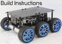
PiBorg schematic
Forums:
Is it possible to get access to the board schematics?
What is the max current input for the Vcc for the RPi- Would another controller board which draws 4A or 2.5A still get enough current from the PiBorg Vcc?
If both motors and the controller board is running the supply can be drained at 5A*2+4A (or 2.5A) for the controller board?
- Log in to post comments


piborg
Sat, 04/27/2019 - 18:33
Permalink
ThunderBorg current
The ThunderBorg provides a maximum of 1.5A for the 5V line. Since the Raspberry Pi will use most of this we normally recommend using a separate 5V regulator to power anything which needs a reasonable amount of power.
The power draw from the ThunderBorg mostly depends on the motors and slightly depends on the power supply voltage. Assuming a 12V power supply / battery the 5V regulator may use up to:
With a 12V supply and motors which could draw up to 5A the worst case usage would be:
We would advise a 0.5 A margin to be safe, so an 11.1 A or better supply would be suitable in this case.
If you did add another 5V regulator to power other boards you would need the supply to handle that current as well.
Lokesh Johri
Sun, 04/28/2019 - 03:00
Permalink
how do you disable the power coming from PiBorg to The RPi?
From MonsterBorg the supply is provided by the header spi/gnd/vcc
If the RPi needs 2.5amp I would provide it separately.
But, will have to disable vcc/gnd from the Thunderborg. How can I do that?
Schematic would really help.
piborg
Sun, 04/28/2019 - 13:19
Permalink
Removing the 5V output from the ThunderBorg
Usually I would suggest connecting the ThunderBorg by cables and leaving the two 5V pins disconnected. This is unfortunately not possible if you have the ThunderBorg directly mounted to the Raspberry Pi as per the MonsterBorg assembly instructions.
What you can do instead is remove the 5V regulator from the ThunderBorg so that it will get 5V power from the Raspberry Pi instead. The ThunderBorg itself only uses 5V to power the LEDs and some of the logic, so it needs very little current.
The 5V regulator is the smaller board attached by three pins to the top of the ThunderBorg (see image below). You can remove this if you are careful by either de-soldering the three pins or using a small pair of side-cutters to break all three pins.
Be warned: Removing the 5V regulator means that the ThunderBorg will no longer be capable of powering a Raspberry Pi and any damage done to the board would be your responsibility.