
Raspio Inspiring support
Forums:
I added the 4 wires to the thunderborg (http://forum.piborg.org/thunderborg/install) but the lights don't work with the example code (tbExternalLedWave.py) No error shown. Thunderborg is found. The voltage level on red/black is 3.3V - but the Inspiring LED board wants 5V, so the whole thing is not working. I even cannot see any logic levels happening on CI/DI with a logic analyzer. What is wrong?
Kind regards,
Markus
- Log in to post comments

piborg
Fri, 03/09/2018 - 11:25
Permalink
RasPiO InsPiRing
You are right that the Vcc connection is supplied from 3.3V. When we tested the functionality all of the InsPiRing boards we had seemed to work fine from 3.3V, they were just not quite as bright. It sounds like we may have just gotten lucky and that they do not necessarily work properly at 3.3V.
What I would suggest is that you remove the Vcc wire from the 5-hole connector and instead connect it to one of the 5V pins on the other side of the ThunderBorg:
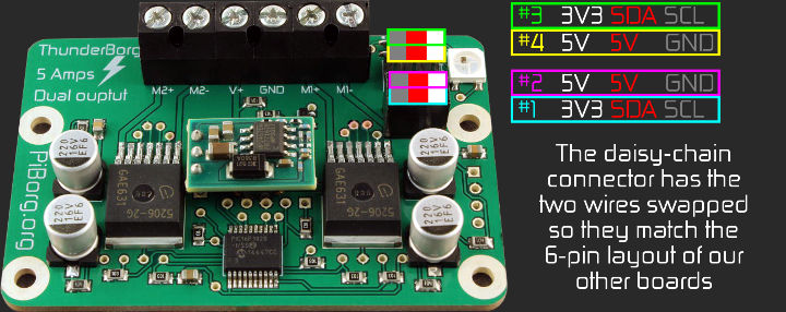
Depending on where you measure the CI / DI signals you may not see anything if the LEDs are not powering up. They should be 3.3V signals which are sent just after the colour change command is sent from the Pi to the ThunderBorg.
mschicker
Sun, 03/11/2018 - 19:19
Permalink
Thanks. This fixed it.
Thanks. This fixed it.