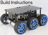
ZeroBorg + Line following
Forums:
Hi
I'm still flogging away with the MagPi "Tiny" robot. After very unsuccessful attempts at the distance measuring, I have put that to one side while I wait for new HC-SR04's to arrive!! It worked fine with the MotoZero but not so far with the ZeroBorg.
In the meantime I'm trying the line follower. I've checked the coding provided by Brian and I understand that it is based on yours (which I haven't been able to find as yet). The GPIO pins in the coding are (BCM) 9, 10, and 11( lines 13 through 15). I was not aware that pins GPIO10 and GPIO11 were available for GPIO. I'm not too sure that BCM 9 is available either. I'm quite happy to allocate others but was just checking the point.
Thanks
HyFy
- Log in to post comments


piborg
Tue, 05/16/2017 - 10:53
Permalink
Line following code
I have had a quick hunt and I cannot seem to find Brian's code anywhere, do you have a link?
BCM 9, 10, and 11 can be used as GPIO, although some boards may also use them as SPI. There is a good reference as to what each pin on the header can do here: https://pinout.xyz/
We do not have a line following example at the moment, I am not sure if Brian's example is based on someone else's code or is his own creation. Either way without being able to look at the code it is hard to point you in the right direction.
What I can say is that the MotoZero uses GPIO to control the motor output directly, whereas ZeroBorg uses I2C to send commands to control the motors. It is likely that the GPIO code you are referring to needs to be swapped for calls into the
ZeroBorglibrary instead.HyFy
Tue, 05/16/2017 - 19:19
Permalink
Line following code link
The link to the code is https://github.com/Corteil/PiMag_Tiny_The_Robot/blob/master/lineFollowin... in the Intro blurb he refers to you!!
I had checked the pinout.xyz and these pins seem to be marked as "SPIO" on some references and so I've steered away from them in the past.
I'm fairly sure that with the Obstacle avoiding code I was using the ZeroBorg library very much the same way that Brian does with the line follower but either way I was getting some amusing ballet dancing and the HC-SR04's got awfully hot!! One pair of motors seem to have reversed themselves but I reversed the code and...
Once I get some new ones I will review things again.
But in the meantime I have this black line around my desk to follow!!
Your help is always appreciated.
piborg
Wed, 05/17/2017 - 10:58
Permalink
Line following code
Now I can see the code it makes a lot more sense :)
Those GPIO pins should be fine for the line sensor, but I am a bit surprised he choose them. Alternatively any other three GPIO pins should work just as well as long as they match the wiring of the line sensor.
His code looks like it should all work fine with a ZeroBorg, it is the motor control part of his code which is based on our standard examples. It seems to use 60% power for turning and 50% power for forwards movement. These can be increased by increasing the
driveLeftanddriveRightvalues.I would suggest you stick with his code as-is and try and check it all works fine before making changes. As far as I can see the sensor should work fine on the GPIO pins he has used and the ZeroBorg control all looks good as well.
HyFy
Wed, 05/17/2017 - 21:29
Permalink
further to the above...
Hi again
I've checked out the line follower code as download from the link in my previous. There are no issues with the GPIOs 9,10,11. BUT... The motors allocated to the steering and their direction is a bit astray. This may have contributed to the obstacle avoidance issues!! The Joystick program works "out of the box" but I would have to keep physically changing 2 motors left and right and their directions (connections) to make any sense out of the line follower program.
I have two other joystick programs both of which use the ZeroBorg. One with various functions to make the steering more progressive and another which uses one thumb stick to operate the left wheels and the other to operate the right wheels. This can make for some very fast turning (and indeed back flips if you're not careful!!). Both derive from the MotoZero but have been adapted for the ZeroBorg.
Any thoughts on the wheel/motor differences between the ZBJoystick and the ZBlineFollower.
Thanks
HyFy
piborg
Thu, 05/18/2017 - 10:18
Permalink
Motor setup
The motor setup is determined by these lines alone in both scripts:
    ZB.SetMotor2(-driveLeft * maxPower)
    ZB.SetMotor3(-driveLeft * maxPower)
    ZB.SetMotor1(-driveRight * maxPower)
    ZB.SetMotor4(-driveRight * maxPower)
In the case above the left motors are 2 and 3, the right motors are 1 and 4. The
-sign swaps which way the motor output runs for forward driving.It should not matter too much which version you use, you should be able to replace the lines in the other script to make it behave the same. I would suggest sticking with the lines above as we found a quirk after releasing our code where positive and negative speeds are not exactly the same from the ZeroBorg. Having all the motors with negative speeds as above produces the best results when trying to drive straight in a forwards direction.
HyFy
Tue, 05/23/2017 - 22:43
Permalink
Thanks for that reply.
Thanks for that reply.
I'm back to the drawing board to see why my having changed the coding as above is not working. I hadn't appreciated that some coders use your advice as to motor layout and others don't do so!!!!
But Thanks for pointing me in the right direction. I just have to get my robot to do the same.
HyFy