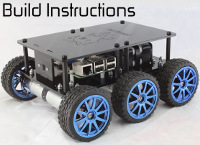
CAD for chassis
Forums:
Hi,
Not sure if this has been asked already (I couldn't find any answers to this)... but do you guys have the CAD drawings for the 2 plates that go on the Diddyborg?
I'm looking to make it bigger by using 18 x 24 inches of stainless steel.
Diddyborg is awesome btw!
- Log in to post comments


piborg
Tue, 05/31/2016 - 14:05
Permalink
DiddyBorg Chassis
We do not have the CAD drawings on the web anywhere
Given that you are intending to resize the plate anyway most of the holes will be in the wrong places.
What you probably need to know is:
https://learn.adafruit.com/introducing-the-raspberry-pi-model-b-plus-plu...
The Pi 2 and 3 use the same holes as the B+
These are 3mm holes spaced 16mm apart
The holes are 8.7mm and 22.7mm in from the edges
Both are 10x3mm rectangles
The gap between them (long sides) is 71mm
Image attached to the bottom of this post
If you have the space I would recommend fitting the board to the top of the bottom plate
This way it will be better protected from rough ground
This is 9.2x4.2mm placed near the PicoBorg Reverse
If you want a top late drawing there is one here:
http://www.thingiverse.com/thing:896741
simark
Wed, 11/02/2016 - 15:29
Permalink
Top-plate drawing
Hi all,
I just wanted to share a simple design I did for the top-plate, in case it can help you. Since I added a Sense Hat to my Raspberry Pi, the 6-pins connector doesn't fit anymore under the top-plate. While trying to drill a hole to pass it, I broke the top-plate in two :(. So I recreated the design, with an additional window to be able to access the Pi more easily, and to allow cables to poke out. I bought some 3mm thick acrylic glass (same as the original) and I went to a local Fablab to use their laser cutting machine.
I attached the SVG to this post and uploaded it there as well: http://nova.polymtl.ca/~simark/rover.svg
Simon